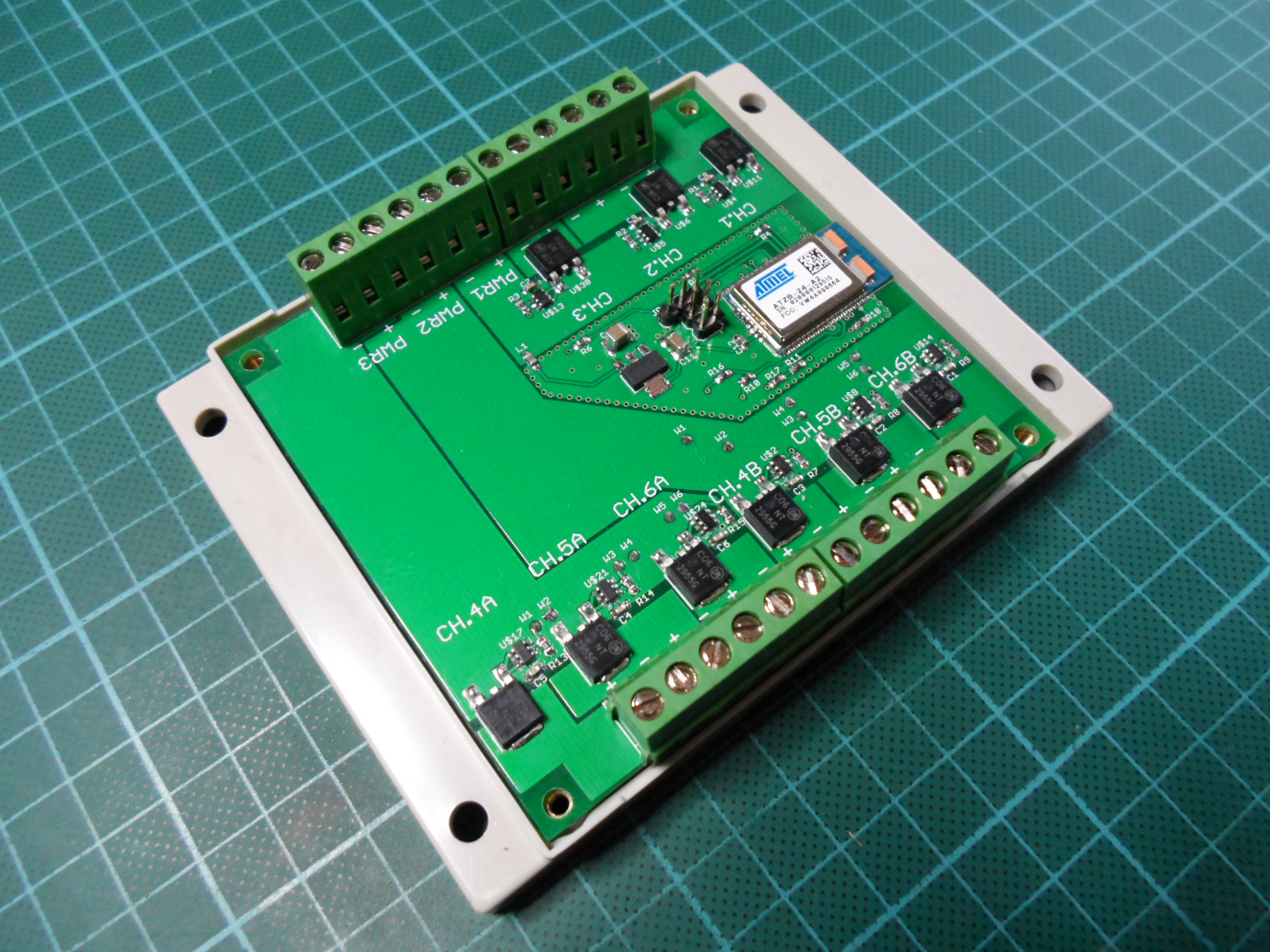
At the beginning of the year, when I sent off the Raspberry Pi 802.15.4 Radio design to Smart Prototyping to have the PCBs manufactured, I also sent off the design for the second Myha home automation device, a six channel LED dimmer that’s intended to control my bathroom light. Unfortunately this design wasn’t quite as successful as the radio interface. It works well enough that I can still use it, but more through luck than anything else.


My bathroom light is made from three loops of LED tape hidden behind plywood coving, which shine out across the ceiling to give a soft, indirect light. There are two loops of warm white LEDs and one loop of RGB, each loop being around 8 meters long. The two white loops are split into two to allow the load to be split across multiple power supplies. Eventually there will be a third loop of white LED tape illuminating a frosted glass floor, which will also be split into two.
To drive these lights I need six channels: ceiling white 1, ceiling white 2, ceiling red, ceiling green, ceiling blue, floor white. The RGB channels need to work with the common cathode tape that I’m using, so need high side switching, and I also need each of the three white channels to be duplicated to two separate outputs.
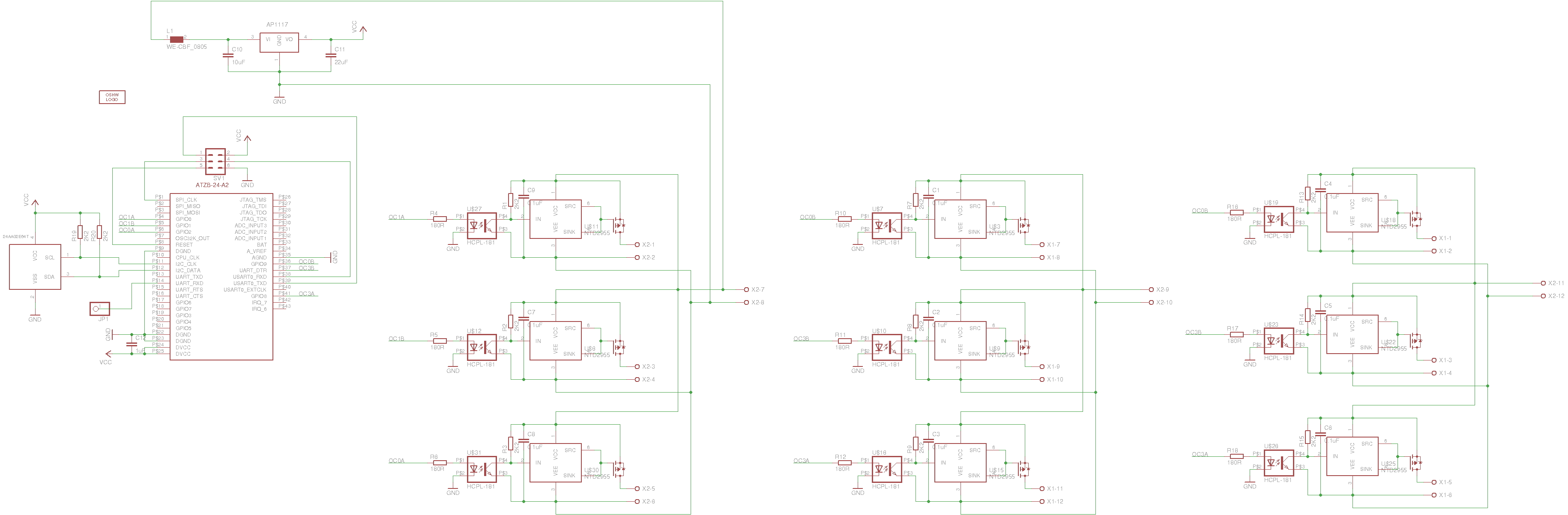
The schematic shown above shows how the design is based around a simple building block consisting of a p-channel MOSFET, a MOSFET driver IC, and an opto-isolator. This block is then duplicated nine times for the nine separate outputs, arranged into three groups of three outputs, with each group being completely isolated from the others to allow them to be powered by separate power supplies. An Atmel Zigbit module controls the outputs via the opto-isolators, and is powered by a 3.3V linear regulator which takes its power from channel group one.
I didn’t spend much time on the design, but I was fairly confident that everything would work as all of the individual pieces were taken from existing working designs. The MOSFET/driver/opto-isolator blocks were taken from the board that I’m currently using to convert the common-anode Rako LED controller to the common-cathode needed by my RGB LED tape, the linear regulator and capacitor combination was taken from my Papilio HDMI Receiver and I’d just finished testing the Zigbit modules on the breadboard.
Linear Regulator Oscillation

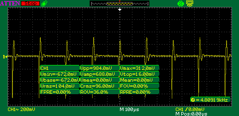
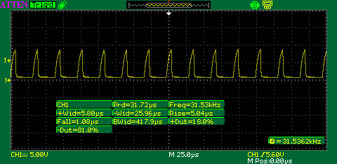
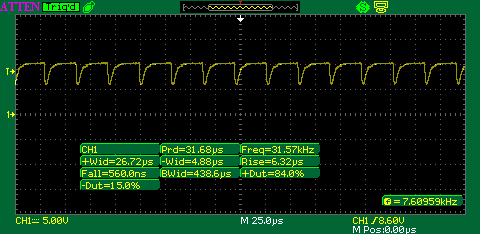
After assembling the board, everything seemed to be working as expected, though there was a faint high pitched whine coming from somewhere whenever the board was powered up. While probing around with the oscilloscope, checking that everything was behaving correctly I found the reason for the whine… the linear regulator was oscillating. The two images above show the oscillation, the saw tooth trace on the left is the output side of the regulator and the trace on the right is the input side.
The regulator that I’m using is an AP1117 from Diodes Inc. The datasheet specifically mentions that the regulator is suitable for use with ceramic capacitors, but what I’d failed to realise is that the datasheet also specifies an ESR (Equivalent Series Resistance) for these capacitors that is near impossible to meet with ceramic capacitors. It requires an ESR between 0R15 and 0R50. The ceramic capacitors that I’m using have a much lower ESR.
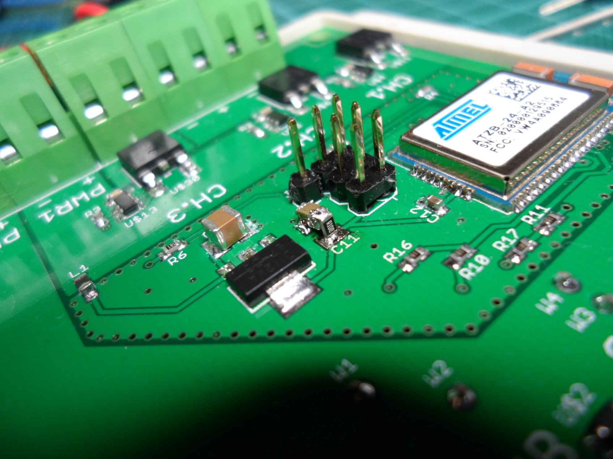
Thanks to a tip from the eevblog forum, I was able to apply a temporary fix without ordering and waiting for some replacement tantalum capacitors to arrive, instead I’ve added a 0R1 resistor in series with the output capacitor, as can be seen in the image above. With the resistor in place the whine has gone and the oscilloscope traces are nice and clean.
Slow Opto-Isolators

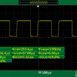
The next issue that I discovered was that I couldn’t dim the LEDs across the full range, most noticeably, they would reach full brightness way before the control slider had reached the end of its movement. The three images above, which show the signal applied to the MOSFET driver for different PWM (Pulse Width Modulator) widths, show the reason for this problem. One thing I hadn’t given much thought to was the speed of the opto-isolators and the frequency of the PWM signal that would drive them.
In the images above, I’m using a 32KHz PWM, which is the frequency you get with no clock divider on a Zigbit module running at 8MHz. That seemed like a nice frequency to use, that had no chance of producing a visible flicker in the light output, but the trouble is, the opto-isolators are far too slow. The images above show that the output of the opto-isolators isn’t rising or falling fast enough to reach a high or a low before it needs to switch again.
Not only does this stop the light from being dimmed across the whole range of 0% to 100%, but it also means that the MOSFETs will be spending most of their time switching rather than being at a steady on or off, and this means they will need to dissipate much more power, which will cause them to overheat.

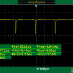
Luckily, there was a simple fix for this problem… I could just reduce the PWM frequency to 4KHz by setting the timer pre-scaler to divide by eight. The images above show the result of doing this. Now the signal driving the MOSFET is much closer to a square wave with most of the time spent in either the fully-on or fully-off state where power dissipation is minimised, and the light can be dimmed smoothly across the entire range.
The opto-isolators are still slower than I would like, but nothing significantly faster is available in the same footprint. A second revision of the board would be better off using a high speed opto-isolator with a Schmitt Trigger action to get really fast edges to drive the MOSFET.
Linear Regulator Power Dissipation
With the two obvious bugs fixed, I wanted to check that nothing would overheat when running at full load, and the two things that have to dissipate power are the MOSFETs and the linear regulator.
I tested the linear regulator first by setting all six channels to 100% with no load attached to any of the MOSFETs. This is the highest current draw that the linear regulator will experience, with nine opto-isolator LEDs drawing 10mA each and the Zigbit module drawing a further 20mA, for a total of 110mA, which was confirmed by the display on my bench power supply.
After a few minutes of this load, the regulator was getting a bit toasty! Not fatally hot, it has an in-built thermal shut down anyway, which wasn’t triggering, but hotter than I’d like. I hadn’t bothered to calculate the power dissipation that the regulator was going to have to handle, just guessing it should be fine at a tenth of the regulators maximum. The trouble is that while the current draw isn’t that high, there’s a huge voltage drop across the regulator, going from 12V to 3.3V.
With a voltage drop of 8.7V and a current consumption of 110mA, the linear regulator has to dissipate a whopping 0.957 Watts. For the SOT-223 package that I’m using, the datasheet gives a junction-to-ambient thermal resistance of 107 degrees Centigrade per Watt and a junction-to-case thermal resistance of 15 degrees Centigrade per Watt.
So, with an ambient temperature of 25 degrees Centigrade I should expect to have a junction temperature of 127.4 degrees Centigrade (0.957 * 107 + 25) and a case temperature of 113 degrees Centigrade (0.957 * (107-15) + 25).
The regulator has a maximum recommended junction temperature of 125 degrees Centigrade and the thermal cut-out should trigger at 150 degrees Centigrade. In other words, at a very modest ambient temperature I’m already beyond the maximum recommended temperature and on the verge of tripping the thermal cut-out. In normal operation however, with the case closed and nine MOSFETs heating things up, I can probably expect an ambient temperature of something nearer 60 degrees Centigrade, if not higher.
Oops!
Luckily, the regulator is outperforming its specification and is stabilising at a case temperature of 75 degrees Centigrade, but this is still too close for comfort, so I plan to replace the linear regulator with a switching regulator such as a TSR-1-2433 or a TR05S3V3. These are both designed to be drop in replacements for 78xx linear regulators and I should just need to make a little adapter board to make them fit the SOT-223 footprint.
Recent Comments