VGA Controller – Timing
-
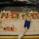
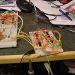
- VGA Timing Board
-
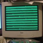
- Horizontal Sync
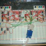
Horizontal timing on the left half of the board: A 25MHZ crystal clocks a 12bit ripple counter, counter output goes to 3 separate 4-to-16 decoders, a collection of AND gates and inverters switch a pair of flip-flops on and off at the right clock counts to produce the horizontal sync.
Vertical timing on the right half of the board, almost identical to the horizontal timing, just clocked by the horizontal sync rather than the crystal.
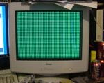
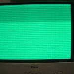
To test the timing a grid is drawn by turning on the green output, controlled by the vertical and horizontal count decoders. The (approximately) correct voltage is achieved by using a resistor and diode so that the green output voltage is one diode drop.
VGA Controller – Pixel Shift Register
-
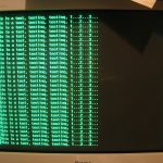
- Shift Register Test
-
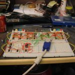
- Shift Register Board
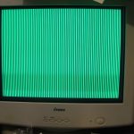
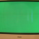
The fixed grid output is replaced by a shift register, the shift register is loaded with the next eight pixels which are then clocked out to drive the green output by the horizontal timing. Once all eight are clocked out the shift register is reloaded.
This test has the input of the shift register hard wired so the pattern is always the same.
VGA Controller – Character ROM
-
- Character ROM Test (Nearly)
-
- Character ROM Test (Working)
-

- Character ROM Test (Closeup)
-
- Character ROM Board
Next a character ROM is added and the output is used to load the shift register. The vertical timing is used for the lower address bits so that each line of output uses the next line of the selected character. In this test the high bits that select the character are hard coded to output a smiley face.
VGA Controller – Memory Addressing
-
- Address Test (Close…)
-
- Address Test (Closer…)
-
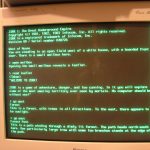
- Address Test (Working)
-
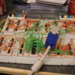
- Address Gen. Board
Now video memory is added, in this test another ROM is used rather than RAM so that the data is always present and doesn’t need a CPU to load it. The output of the video memory is used to set the upper bits of the character ROM address and therefore select the character to be displayed.
The lower right corner of the board contains the logic that addresses the video memory. It has to increment through the first 80 characters, then repeat those first 80 characters 16 times to output all lines of the first row of text, then move onto the next 80 characters and repeat those 16 times, then onto the next line, repeating for all of the lines.
Each character is 8×16 pixels which makes the logic much simpler as the divisions are just shifts, with the 640×480 VGA timing this gives us 80×30 characters, requiring 2400 bytes of video memory.
PS/2 Keyboard Controller
-
- PS/2 KB Board
With text video output working a PS/2 keyboard controller is added based around a serial-in-parallel-out shift register.
Recent Comments