 This is a project that I’d been planning on doing for the last 8 years (and I’ve even had most of the part waiting on the shelf for that long). It all started shortly after I got the SIEG milling machine back in 2014, when I ran into this page on macpod.net describing how to add an RPM readout. Well… here we are close to a decade later and I finally got it done, though I did end up doing it in a completely different way (and didn’t use any of the parts).
I’d originally been planning on doing this with a microcontroller, pretty much exactly as described on macpod.net, but coming back to it now and re-reading the protocol description, it occurred to me that it doesn’t actually need a microcontroller. Instead it can be done with a set of shift registers.
The Protocol
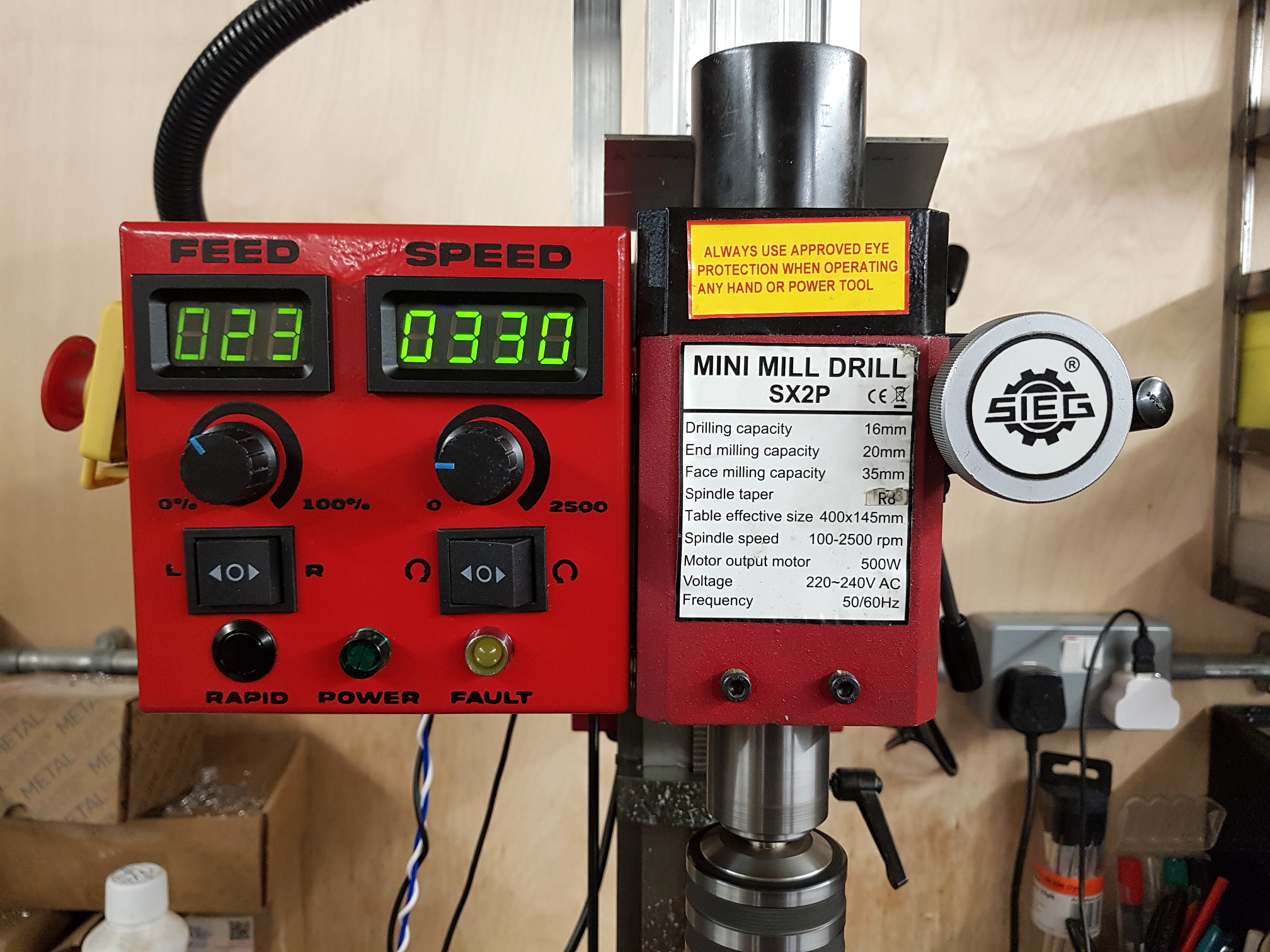
There’s a great description of the protocol on macpod.net, but I’ll summarise it here. The mill has three signal lines to drive the RPM display… Chip Select, Clock, and Data In (which is feeling a bit SPI like). It sends regular bursts of data that end with 8 bits of address and 9 bits of data. I say “ends with” as some versions prepend a header and some don’t, but as we’ll see, we don’t really care if there’s a header, we’ll only be looking at the end of the data.
Each burst of data updates one digit of the display, as indicted by the address. There are four addresses, only three of which are really useful:
| Address | Description |
|---|---|
| 0xA0 | Thousands digit |
| 0xA1 | Hundreds digit |
| 0xA2 | Tens digit |
| 0xA3 | Other display elements |
The 9 bits of data are an always-zero bit followed by 8 bits indicating which 7 segment elements should be on. The eight bits cover the seven main elements plus the decimal point. These bits can be used to directly drive a 7 segment display, no decoding required. The units digit is always zero and can be hard wired to always display that.
Decoding With Shift Registers
With the signal names being reminiscent of SPI and the data not needing any decoding to drive seven segment LEDs, I was wondering if it could be done with just a few shift registers.
At first it seems that having 17 bits of data is going to be a bit awkward. Standard shift registers have 8 bits, so two of them will only hold 16, and adding a third for one extra bit would a waste. However that 17th bit actually helps, it’s always zero so we don’t actually need to look at it, but it gives us one extra clock cycle to decide if we want to display the received data (I wonder if the official display is also using shift registers?).
Simulation
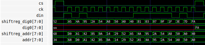
Here cs (Chip Select), ck (Clock), and din (Data In) are the input signals. shiftreg_addr and shiftreg_dig0 are the two shift registers, chained together so that the incoming data first goes into shiftreg_dig0 and then overflows into shiftreg_addr. addr is the registered output of shiftreg_addr, and dig0 is the registered output of shiftreg_dig0.
These 17 bits will be setting the 1000’s digit, so we’re expecting an address of 0xA0. Looking at the simulation output we see that after the first 8 bits come in, shiftreg_dig0 contains 0xA0. After another 8 bits of incoming data we can see that this has been shifted through to shiftreg_addr, and shiftreg_dig0 contains most of the 7 segment display data. It still has the always 0 bit and doesn’t yet have the decimal point bit.
However, the value in shiftreg_addr isn’t yet available for use. It still needs to be registered onto the parallel outputs of the shift register. That happens when bit 17 arrives… after which the address is on shiftreg_addr‘s parallel output (addr), the useless always-0 bit has moved from shiftreg_dig0 to shiftreg_addr, and shiftreg_dig0 now contains all 8 bits of the 7 segment data.
We can now use the address value to decide if we want to register shiftreg_dig0‘s value onto its parallel output, which drives the LEDs in the 7 segment display. If it’s the correct address then we allow the cs signal going high to feed into the register clock of shiftreg_dig0, which will move the value to the output and update the display. If it’s not the correct address then the data just gets ignored.
These two shift registers are enough to drive one digit, but we need to drive three… the 1000’s, 100’s, and 10’s. As mentioned earlier, the units digit will be hard wired to zero. To do this we just have to add two more shift registers, so there’s one register for each digit and one for the address. The incoming data goes into each digit’s shift register in parallel, then one of them also overflows into the address register.
Schematic
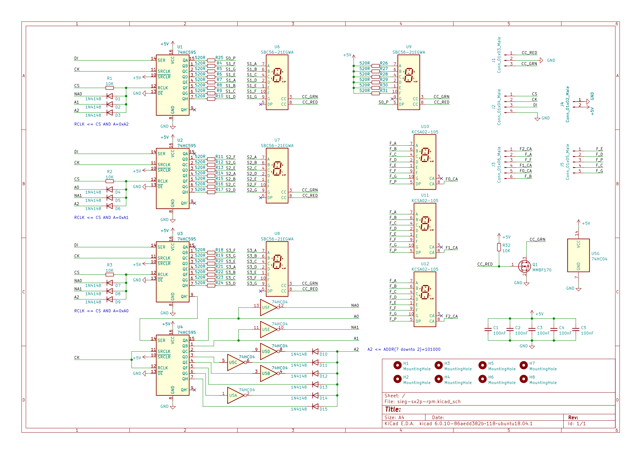
The address decoding that triggers the latching is done with a few inverters and a whole lot of diodes (15 of them!). The diodes are used to implement AND logic, with the inverters flipping the bits where we want to check for the opposite value. Luckily it ends up needing six inverters which is exactly what’s provided by a single hex inverter chip. This address decoding logic can be seen in the schematic on the right.
An additional feature worth mentioning in the schematic is the colour change for the RPM display, which shows the mill spindle directon. An additional pole in the forward/reverse switch is used to pull either the green common cathode, or the red common cathode to ground. This means that the display is normally green, but if the mill spindle is reversed, the display will tun red, which will hopefully save a few drills and end mills. There’s a mosfet to pull down the green common cathode if the switch is in the neutral position, which mirrors the mill’s default direction.
A New Control Box
A year or two ago I built an X-axis power feed for the mill. It’s essentially a scaled down version of Phil Vandelay’s design. I’d never got around to making an enclosure for its controls, and just had the motor control board and potentiometer laying loose on the bench next to the mill.
Now I was adding an RPM display, it seemed like a good opportunity to build a whole new control box that could integrate the RPM display, a spindle forward/reverse switch, and the power feed controls.
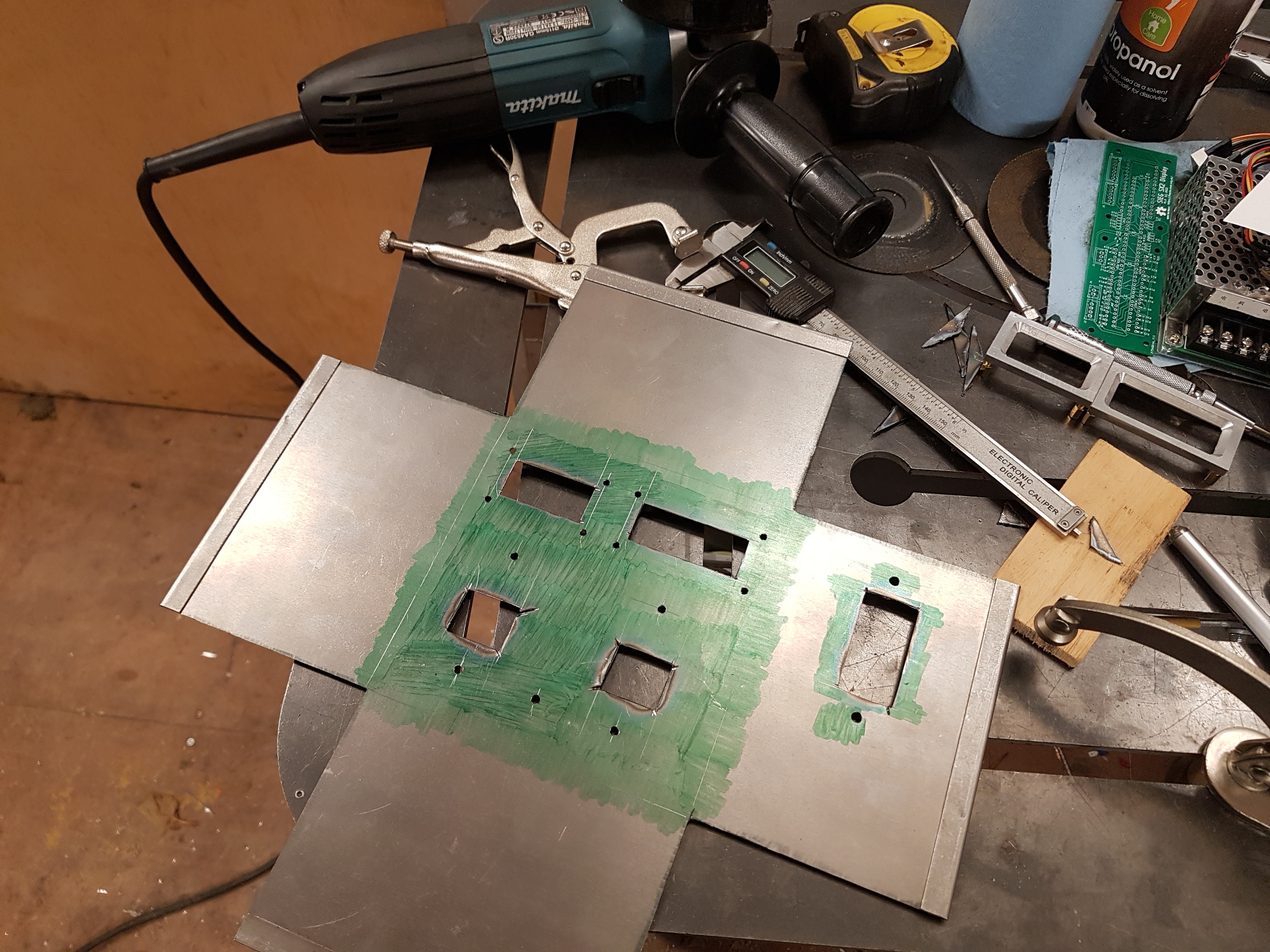
Cut out a mirror image
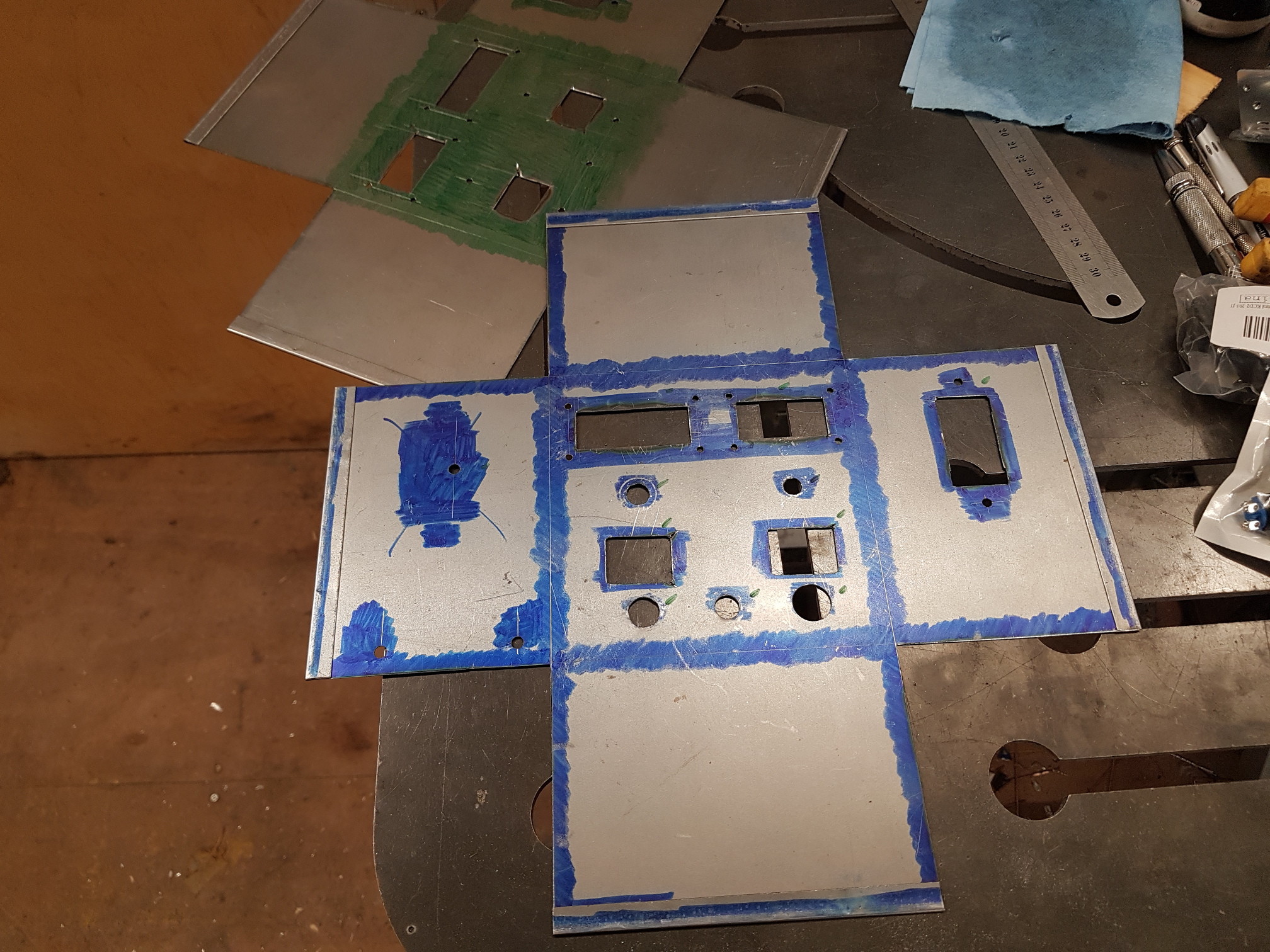
Then cut it right
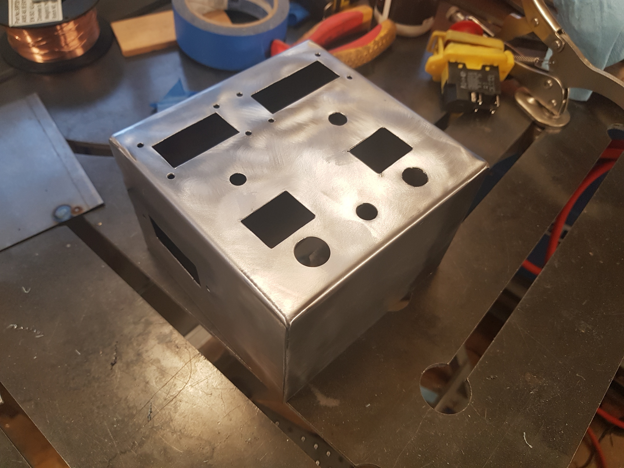
And weld it together
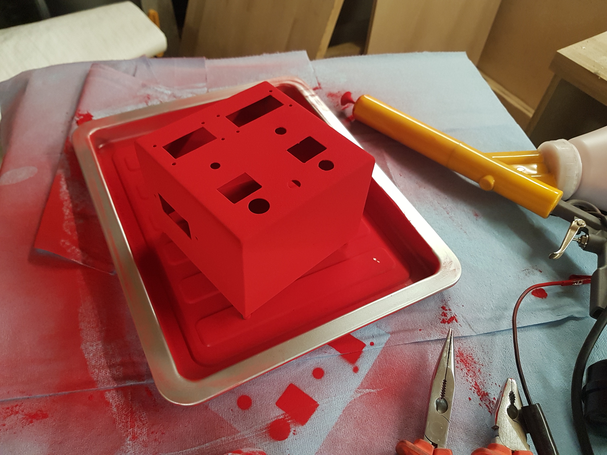
Base Coat
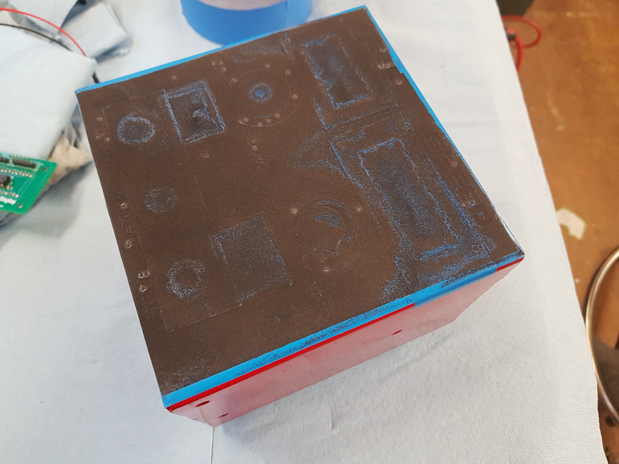
Vinyl Mask Text
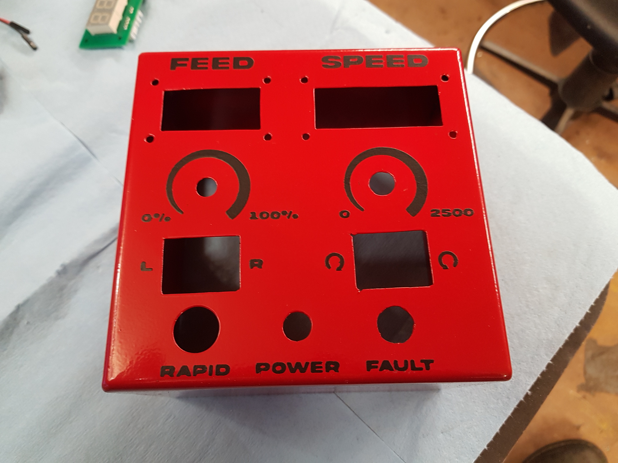
Powder Coat Complete
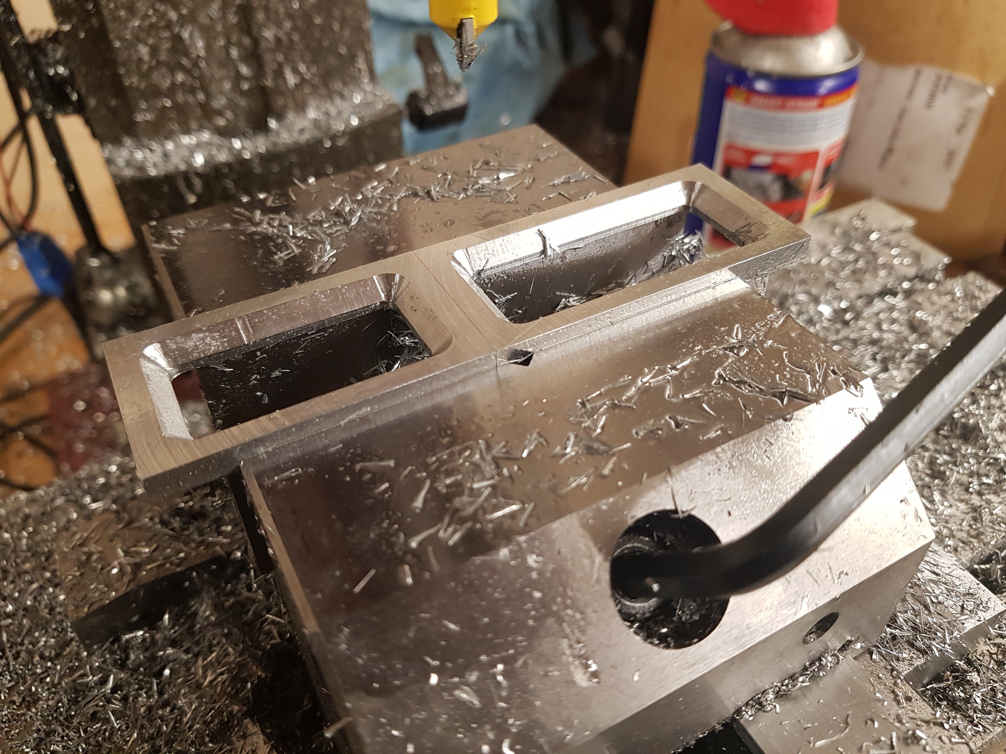
Machining Bezels
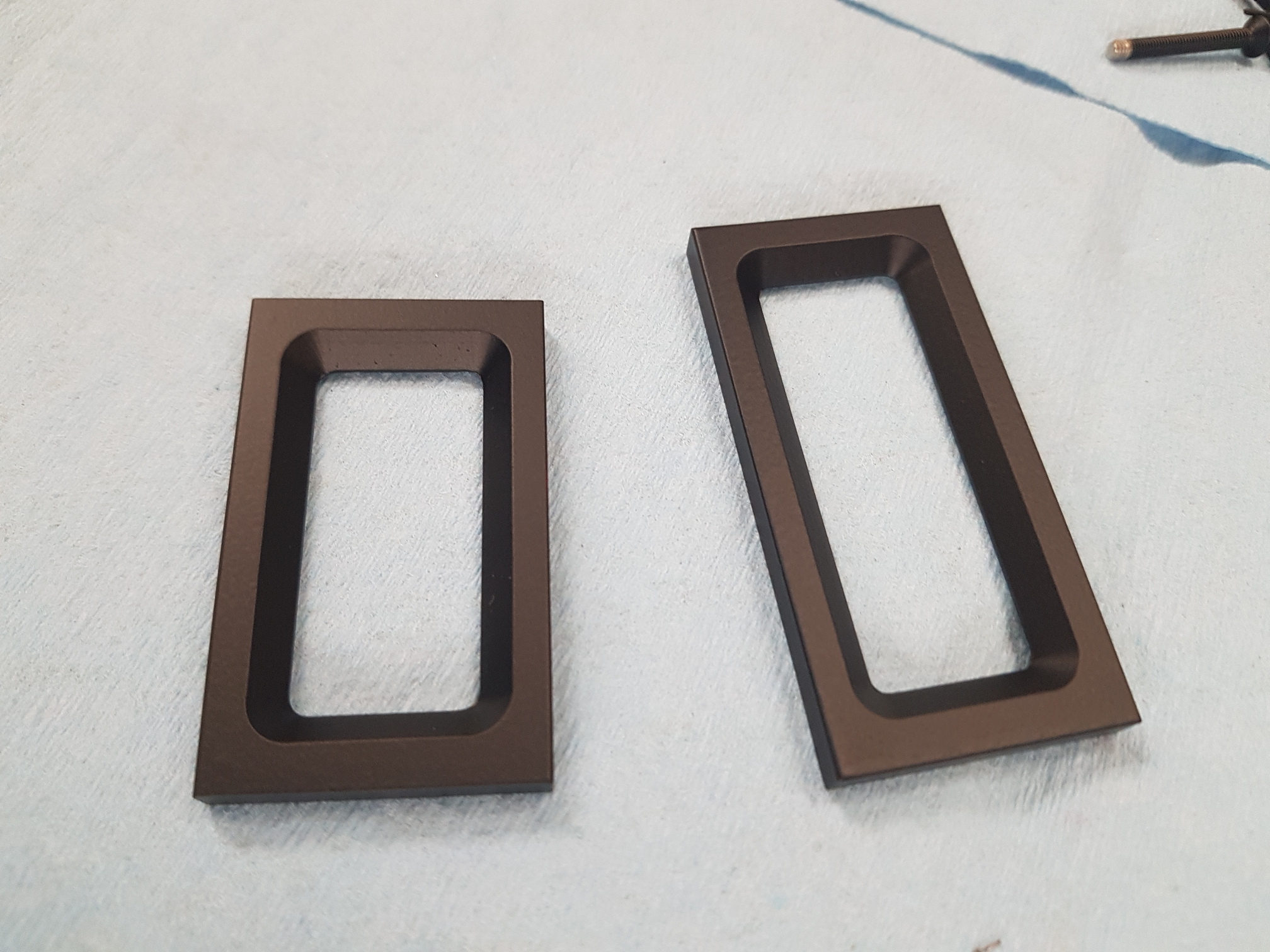
Powder Coated Bezels
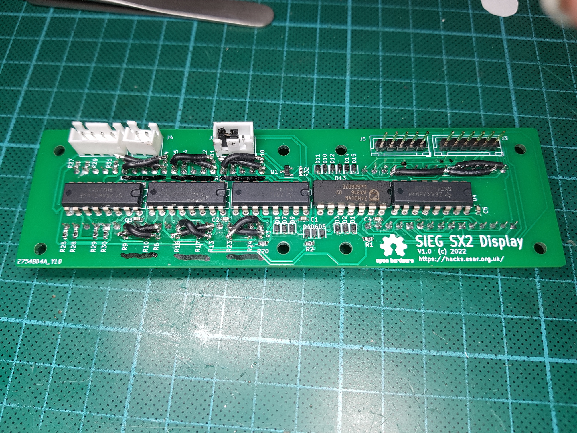
PCB Full Of Bodge Wires
Wrapping It All Up
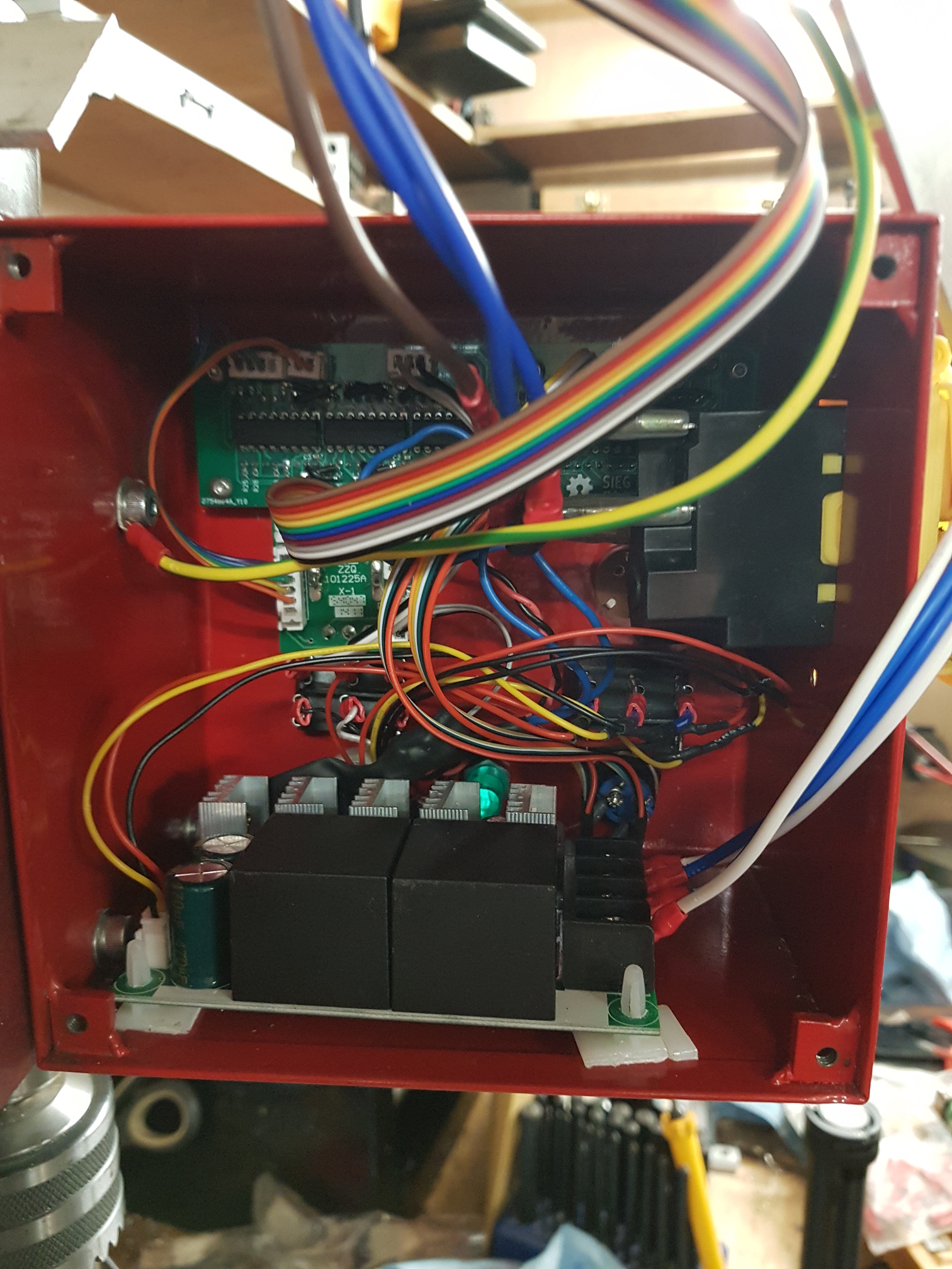
Cramming It All In
Closing It Up
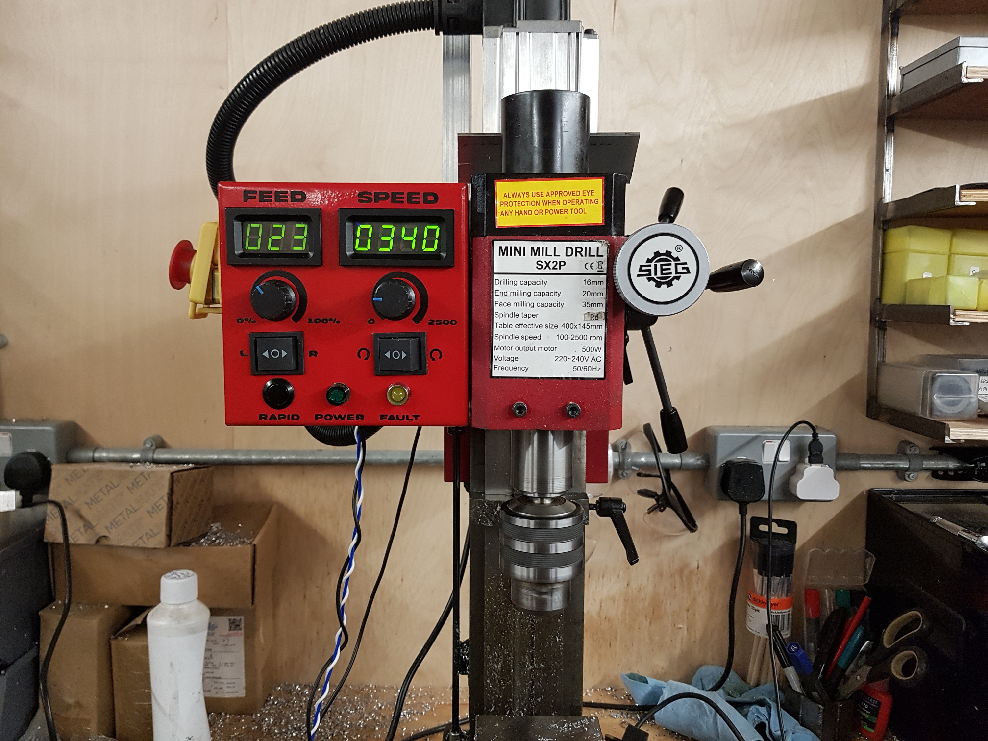
Finished
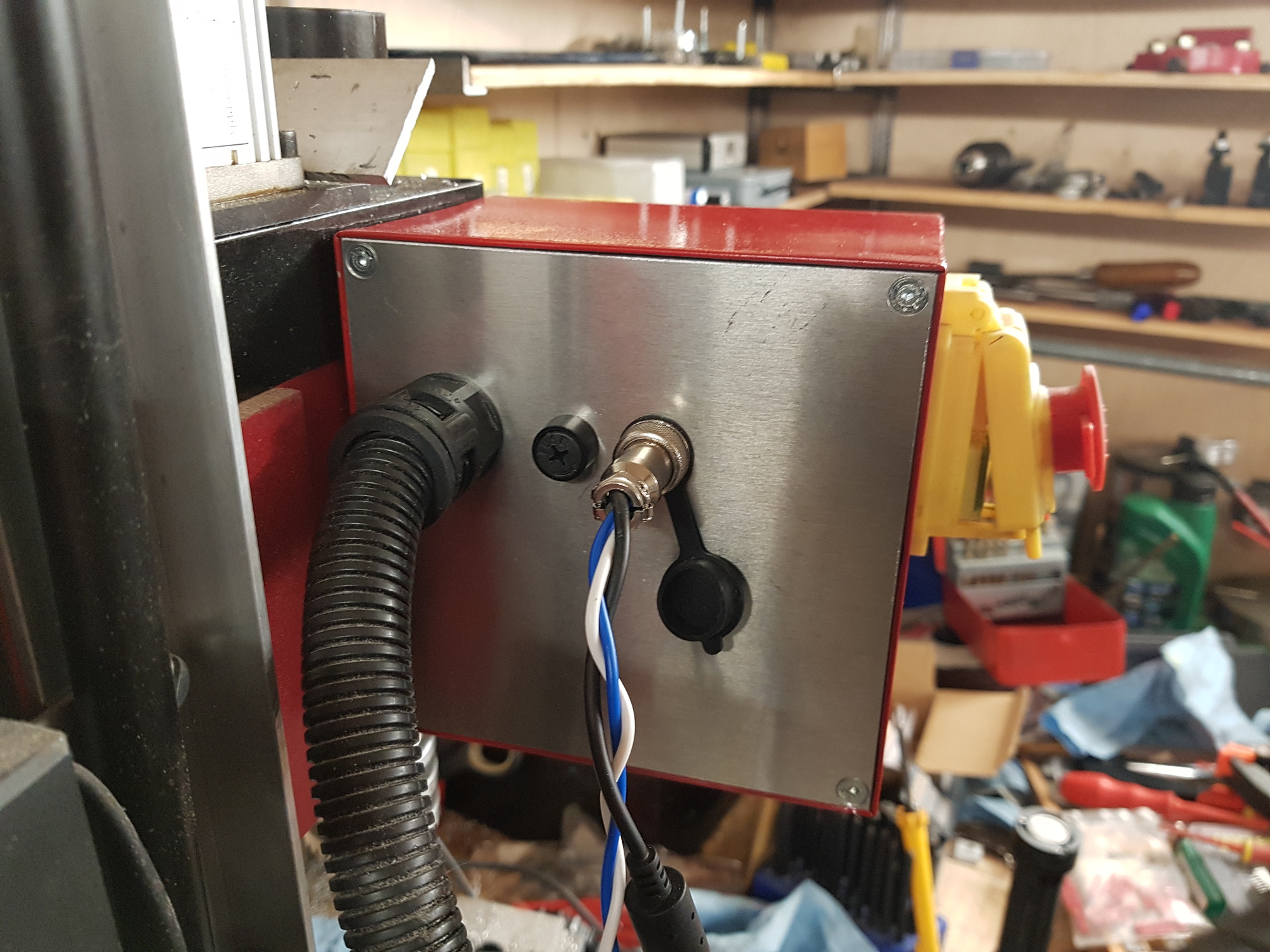
The box is closed by an aluminium panel that brings in the mill’s original cable bundle and the original fuse holder. Finally there’s a new socket to bring 18V power in to the x-axis motor board, and its output to the motor (I’m over-driving the 12v windscreen motor to get a faster rapid)
So… is there an actual advantage to doing this with shift registers instead of a microcontroller? Not really, no. It’s not cheaper, it’s not got a lower parts count. About the only advantage I can think of is the display isn’t multiplexed, so has zero flicker. That, and it doesn’t need programming. But it was an interesting challenge to do it differently.
The Files
The KiCad schematic and PCB files can be found in github here
Recent Comments