As I’ve been making more custom automation devices, I’ve come to the realisation that I don’t actually have to be restricted by the limitations of the Rako protocol. I could start again from scratch with my own custom protocol and have no restrictions at all.
The latest annoyance that’s triggered this line of thought is caused by the Rako protocol being one way. It’s possible to tell a device to go to a certain brightness level but it’s not possible to ask it what its current level is. Up until now this limitation has only manifested itself in the iPhone/Android app, where the level sliders are always at zero when the app is opened, which is a fairly minor annoyance. However, it’s now become a problem with my bathroom light touch switch.
The problem occurs because the touch switch and the dimmer are disconnected and only communicate wirelessly, and because the touch switch relies on knowing the current state of the light so that it can alternate between turning the light on or off for each press. This means that if a message goes missing due to interference or some other reason, then the switch and the dimmer are out of sync and it takes three presses of the switch before they’re back in sync again, all with no visible feedback to the user that anything is actually happening at all.
If the protocol was bi-directional then this wouldn’t be an issue as the switch would always be able to find out the actual state of the light, so… time for a new protocol.
Radio Transceiver
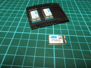 I started out by searching the Farnell catalogue for radio transceiver modules, with the criteria:
- They should be self contained so that I don’t have to worry about RF board layouts
- They should be small so that they could fit behind a light switch
- They should be able to get reliable coverage thoughout a house
- They should be cheap
In the end I decided to use Atmel Zigbit modules, which combine an ATmega1281 microcontroller, a 2.4GHz 802.15.4 radio transceiver and a chip antenna, and are intended to be used with the Zigbee protocol. These certainly meet the first two criteria, but they are a bit expensive at £20 in single unit quantities, though that’s offset a bit by not needing a separate microcontroller.
As they operate at 2.4GHz the signal isn’t going to get around the house anywhere near as well as the 433MHz devices used by Rako, in fact I’d guess they’ll be lucky to get through more than one wall. However, in reality they should be much better than the Rako radios as they’re meant to operate in a mesh network rather than point-to-point, so each individual radio link only needs to go a few meters before it finds another device in the mesh. So it should be possible to cover fairly huge areas, certainly much bigger than my house.
Transport Protocol / Software Stack
 When I ordered the modules, I’d originally intended to use the Zigbee protocol and BitCloud, the free-to-use Zigbee implementation from Atmel. There’s even a sub-protocol within the Zigbee standard for home automation. However it turns out that the software stack, while free, is closed source and reportedly a bit buggy, and really needs a Windows machine for development, all of which made me think twice about whether I really wanted to tie myself into this software stack.
I had a hunt around for an open source Zigbee stack, but FreakZ, which is the only project I could find, seems to have been abandoned by its author after falling out with the Zigbee Alliance, who control the specification, and who also expect to be paid for any commercial use of the protocol, which is yet another reason to avoid Zigbee.
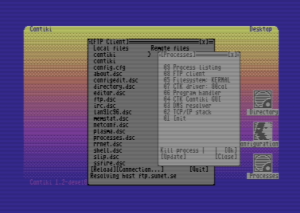
While I was looking for an open source Zigbee stack I came across Contiki. I’d seen Contiki in a story on Slashdot a few years ago, where it was running a web browser and IP stack on a Commodore-64. At the time I hadn’t paid it much attention and assumed that that was all it did, but it turns out its real purpose isn’t web browsing on a Commodore-64. It’s actually a tiny operating system designed to run on heavily resource constrained systems, like 8-bit microcontrollers, and is used a lot for wireless sensor networks.
Not only are a lot of those wireless sensor networks running over 802.15.4, but Contiki has already been ported to the Atmel Zigbit modules. It also has a fully compliant IPv6 and 6LoWPAN stack and can operate in a mesh network using the RPL routing protocol. Contiki itself is open source and all of these protocols are completely free and open.
With all of that in mind Contiki and IPv6 seemed like a much better choice than Zigbee and is what I’ve decided to use. It also has the added bonus, that after years of hearing people describe IPv6 as having a big enough address space to give every light bulb its own address, I can actually go ahead and give every light bulb and switch in my house an IP address!
Application Protocol

Unlike Zigbee and its predefined support for home automation, using IPv6 just provides UDP and TCP and I still needed an application protocol. Rather than build a completely custom protocol I decided to use MQTT as a base, which is a very simple and lightweight protocol that’s primarily intended for delivering telemetry data from sensors.
It works on a publish/subscribe system with a message broker. Sensors publish data to named locations (called “topics”) whenever and as often as they want. Other parts of the system can subscribe to those topics and will receive a message whenever new data is published.
A home automation system is essentially the reverse of a sensor network. Instead of having many sensors publishing data which is subscribed to by a small number of devices, there is instead a small number of publishers: the light switches and control application, and many subscribers: the lights, blinds, door locks, etc.
So for my home automation system I could have each light dimmer subscribe to a MQTT topic named “[IPv6_Address]/level”, where “[IPv6_Address]” is the individual dimmer’s address, then the control application on my phone (or a light switch) could publish a new value to the dimmer’s topic whenever it wanted the level to change.
Connecting to the Modules
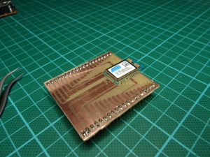
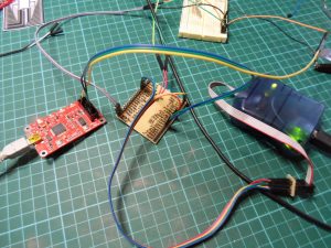 With a rough idea of how the system should work I could build a proof of concept prototype. The first job was to make a pair of breakout boards for two of the modules, so that I’d have some way to connect them to a breadboard, and to make them a bit more prototype friendly than they normally are with their 1mm pitch SMD footprint.
Once the modules were mounted on breakout boards I could attach an ISP programming header (pinout in the table below) and connect the module’s UART to my laptop via a BusPirate, ready to see any output it might generate.
NOTE: The UART pins on the Zigbit modules are labelled backwards, so rather than connecting RX to TX and TX to RX as would be normal, it should be wired RX to RX and TX to TX.
| ISP Pin | ISP Name | Zigbit Pin | Zigbit Name |
|---|---|---|---|
| 1 | MISO | 39 | USART0 TXD |
| 2 | VCC | 24/25 | VCC |
| 3 | SCK | 1 | SPI CLK |
| 4 | MOSI | 38 | USART0 RXD |
| 5 | RESET | 8 | RESET |
| 6 | GND | 22/23 | GND |
Hello Contiki World
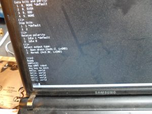 The next step was to build the Contiki hello-world example, but before that a couple of changes had to be made to the zigbit platform files within Contiki.
Rather than using the official Contiki source tree I’m actually using the version from the 6lbr project, the reason for which will become clear later on. The 6lbr version can be retrieved from the 6lbr github.
However, the following changes also apply to the official Contiki source tree.
The first and most important change was to adjust the serial port baud rate from the default 115200 to 38400. Apparently the UART in the Zigbit modules can’t reliably do 115200. This was changed in platform/avr-zigbit/contiki-avr-zigbit-main.c:
-  rs232_init(RS232_PORT_1, USART_BAUD_115200,
+  rs232_init(RS232_PORT_1, USART_BAUD_38400,
The second change was in the same file and just turns on some debug messages to make it more obvious if things are working:
-#define ANNOUNCE_BOOT 0    //adds about 600 bytes to program size
-#define DEBUG 0
+#define ANNOUNCE_BOOT 1    //adds about 600 bytes to program size
+#define DEBUG 1
The third and final change was made in platform/avr-zigbit/Makefile.avr-zigbit, changing the definitions for the programming device from jtag2 to avrispmkii:
-AVRDUDE_PROGRAMMER=jtag2
-AVRDUDE_PORT=usb:00B000000D79
+AVRDUDE_PROGRAMMER=avrispmkii
+AVRDUDE_PORT=usb
Next the fuse bits needed to be changed in the Zigbit module so that it would run at 8MHz:
avrdude
Then the hello-world example could be built:
cd examples/hello-world
make TARGET=avr-zigbit
The EEPROM contents could be uploaded (which contain the MAC address):
make TARGET=avr-zigbit hello-world.eu
And the code could be uploaded:
make TARGET=avr-zigbit hello-world.u
NOTE: Appending “.u” to the target name gets the Makefile to upload the code, and appending “.eu” gets it to upload the EEPROM contents. Alternatively they can be manually extracted from the ELF file and uploaded using avrdude, like so:
avr-objcopy -j .eeprom --set-section-flags=.eeprom="alloc,load" --change-section-lma=.eeprom=0 -O ihex hello-world.avr-zigbit eeprom.hex
avr-objcopy -R .eeprom -R .fuse -R .signature -O ihex hello-world.avr-zigbit 6lbr-demo.avr-zigbit.hex
avrdude -v -P usb -c avrispmkii -p atmega1281 -U flash:w:hello-world.avr-zigbit.hex
avrdude -v -P usb -c avrispmkii -p atmega1281 -U eeprom:w:eeprom.hex
Hello 802.15.4 World
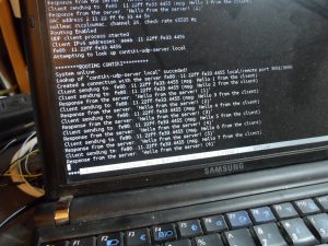 With the Contiki hello-world example working, it was time to see if the radios were working by running the UDP client and server from the udp-ipv6 example on a pair of modules.
This was almost as simple as just running make and then uploading the client to one module and the server to another, but doing so doesn’t actually work… they both get the same MAC address, and as a result, they can’t talk to each other.
When building for the avr-zigbit target, the MAC address is hard-coded in platform/avr-zigbit/contiki-avr-zigbit-main.c, and needs to be changed for one of the two:
-uint8_t mac_address[8] = {2, 0, 0, 0, 0, 0, 0xaa, 0xaa};
+uint8_t mac_address[8] = {2, 0, 0, 0, 0, 0, 0xaa, 0xbb};
Once the two modules had different MAC addresses they started talking to each other shortly after power-up, printing the messages they were exchanging to the UART.
Routing Between Ethernet & 802.15.4
 I want the main control for the lights to be an app on my phone, so the next part I needed to get working was routing between the wireless network and my main Ethernet network.
It turns out that even though the zigbit modules are talking IPv6 over the wireless network, and my main Ethernet network is running IPv6, connecting the two isn’t as simple as it might seem. There are lots of little details that need handling, for example the main Ethernet network uses ICMPv6 based neighbour discovery, but the wireless network doesn’t, it uses a neighbour discovery mechanism optimised for the 802.15.4 network.
Luckily, it can all be handled by the 6lbr router, which is why I’m using their Contiki source tree and not the official one.
To get the routing working I installed Raspian onto a Raspberry Pi, built and installed 6lbr on the Raspberry Pi, and connected the UART from one of the Zigbit modules to the UART on the GPIO header on the Raspberry Pi (via a couple of 1K resistors, without which the zigbit module would fail to start). I then built examples/ipv6/slip-radio and uploaded it to the Zigbit module that was attached to the Raspberry Pi.
The activity of 6lbr can be followed in /var/log/6lbr/6lbr.log, after it starts it prints messages complaining about an inability to get a MAC address, powering up the attached Zigbit module at this point allows it to get a MAC address and it then begins routing between the two networks. Powering up the Zigbtt module before 6lbr starts leaves 6lbr unable to get a MAC address.
By default the 6lbr router uses the subnet bbbb::/64 on the Ethernet side and aaaa::/64 on the wireless side. The router itself has the address bbbb::100, pointing a web browser to http://[bbbb::100]/ shows a web interface that has various statistics and a graph showing the structure of the wireless network.
NOTE: Running the web browser on the Raspberry Pi doesn’t work, it must be on another machine on the Ethernet network, the Raspberry Pi itself can’t access bbbb::100.
Once 6lbr was running I added a route to the wireless network to my main desktop machine:
ip -6 route add aaaa::/64 via bbbb::100
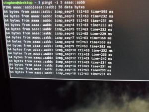
At which point I was able to ping the second Zigbit module (the one not attached to the Raspberry Pi) from my desktop:
ping6 aaaa::aabb
Timers & PWMs
One of the advantages of using the Zigbit modules is that they have a very capable microcontroller built in, which should be suitable for implementing pretty much any home automation device. One device I’m going to need a lot of is dimmers, which ideally need hardware PWMs (Pulse Width Modulators), so I want as many useable PWMs as possible.
After looking to see which of the ATmega1281’s pins are available on the Zigbit module’s pins (see the table at the bottom of the page), I could see that I could have six PWMs if I had access to timers 0, 1 and 3. However, reading the avr-zigbit platform support code in Contiki revealed that timers 0 and 3 were in use, which would mean I would only have two PWMs, which isn’t even enough for a single RGB device.
While I was checking which timers were in use, I noticed that there were some #defines which could move Contiki’s main clock to timer 2, provided timer 2 was driven by an external 32kHz crystal. As luck would have it, the Zigbit modules have this crystal, so moving the clock from timer 0 to timer 2 was as simple as adding one #define to platform/avr-zigbit/contiki-conf.h:
#define AVR_CONF_USE32KCRYSTAL 1
Freeing up timer 0 meant I now had four PWMs, but it would be nicer still if I could have all six. The ATmega1281 has five timers and timers 3, 4 and 5 are functionally identical, so it seemed logical that moving Contiki’s rtimer from timer 3 to timer 5 should just be a case of finding all of the accesses to the timer 3 registers and replacing them with timer 5 registers. Ignoring a few issues when I missed some of the places the registers are accessed, it was this simple, so I now have six hardware PWMs and the timer usage looks like this:
| Timer | Original Usage | Modified Usage |
|---|---|---|
| Timer0 | Contiki Clock | Unused / 2xPWM |
| Timer1 | Unused / 2xPWM | Unused / 2xPWM |
| Timer2 | Unused | Contiki Clock |
| Timer3 | Contiki rtimer | Unused / 2xPWM |
| Timer4 | Unused | Unused |
| Timer5 | Unused | Contiki Rtimer |
Six Channel Dimmer Prototype
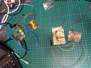
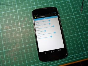 With everything else working, I just needed a few bits of software to get a working prototype of a six channel dimmer.
First I needed an MQTT message broker, so I temporarily installed Mosquitto on my desktop machine. I intend to eventually run this on the Raspberry Pi that’s routing between Ethernet and 802.15.4, but at the moment, even though it’s doing the routing, the Raspberry Pi is the one machine that can’t actually access the 802.15.4 network. So until I iron out the routing issues Mosquitto is running on my desktop.
Next I needed an Android app to control the dimmer, so with the help of the Eclipse Paho MQTT client library, I wrote a very quick and dirty app with six sliders that publish their positions to the Mosquitto message broker.
Lastly I needed to implement the dimmer itself, which needed an MQTT client for Contiki, which surprisingly, I wasn’t able to find. So, I spent a couple of days writing an MQTT client for Contiki, before finally adding the 100 or so lines of code necessary to implement a simple six channel dimmer, which is what the video at the top of the page demo’s.
Here’s what the dimmer code looks like:
PROCESS_THREAD(mqtt_client_process, ev, data)
{
  static uint8_t in_buffer[64];
  static uint8_t out_buffer[64];
  static uip_ip6addr_t server_address;
  static mqtt_connect_info_t connect_info =
  {
    .client_id = "contiki",
    .username = NULL,
    .password = NULL,
    .will_topic = NULL,
    .will_message = NULL,
    .keepalive = 60,
    .will_qos = 0,
    .will_retain = 0,
    .clean_session = 1,
  };
  static const char* topics[] =
  {
    "0", "1", "2", "3", "4", "5", NULL
  };
  PROCESS_BEGIN();
  uip_ip6addr(&server_address,
              0xbbbb, 0, 0, 0, 0, 0, 0, 0x110);
  TIFR0 = 0;
  TIMSK0 = 0;
  OCR0A = 64;
  OCR0B = 64;
  TCCR0A = 0xA3;
  TCCR0B = 1;
  OCR1A = 128;
  OCR1B = 128;
  OCR1C = 128;
  TCCR1A = 0xA1;
  TCCR1B = 0x09;
  OCR3A = 128;
  OCR3B = 128;
  TCCR3A = 0xA1;
  TCCR3B = 0x09;
  PORTB |= (1 << PORTB7);
  PORTG |= (1 << PORTG5);
  DDRB |= (1 << DDB7); // OC0A is output
  DDRG |= (1 << DDG5); // OC0B is output
  DDRB |= (1 << DDB5); // OC1A is output
  DDRB |= (1 << DDB6); // OC1B is output
  DDRE |= (1 << DDE3); // OC3A is output
  DDRE |= (1 << DDE4); // OC3B is output
  PROCESS_PAUSE();
  mqtt_init(in_buffer, sizeof(in_buffer),
            out_buffer, sizeof(out_buffer));
  mqtt_connect(&server_address, UIP_HTONS(1883),
               1, &connect_info);
  PROCESS_WAIT_EVENT_UNTIL(ev == mqtt_event);
  if(mqtt_connected())
  {
    static int i;
    for(i = 0; topics[i] != NULL; ++i)
    {
      mqtt_subscribe(topics[i]);
      PROCESS_WAIT_EVENT_UNTIL(ev == mqtt_event);
    }
  }
  else
    printf("mqtt service connect failed\n");
  while(1)
  {
    PROCESS_WAIT_EVENT_UNTIL(ev == mqtt_event);
    if(mqtt_event_is_publish(data))
    {
      const char* topic = mqtt_event_get_topic(data);
      const char* message = mqtt_event_get_data(data);
      int level = 0;
      while(*message != '\0')
        level = (level * 10) + *message++ - '0';
      printf("Setting level: %c = %u\n", topic[0], level);
      switch(topic[0])
      {
        case '0':
          OCR0A = level;
          break;
        case '1':
          OCR0B = level;
          break;
        case '2':
          OCR1A = level;
          break;
        case '3':
          OCR1B = level;
          break;
        case '4':
          OCR3A = level;
          break;
        case '5':
          OCR3B = level;
          break;
      }
      printf("publishing change...\n");
      sprintf((char*)message, "%u", level);
      mqtt_publish("newval", message, 0, 1);
    }
  }
  PROCESS_END();
}
ATmega1281 Pins
For reference, here’s how the pins on the ATmega1281 are used in the Zigbit modules:
Pins Reserved
| Pin | Function | Usage |
|---|---|---|
| PA0 – 6 | AD0 – AD6 | Not Connected |
| PA7 | AD7 | Radio Reset |
| PB0 | /SS | Radio SPI Select |
| PB4 | OC2A, PCINT4 | Radio SLP |
| PC0 – 7 | A8 | Not Connected |
| PE5 | OC3C, INT5 | Radio IRQ |
| PG3 | TOSC2 | 32kHz Oscillator |
| PG4 | TOSC1 | 32kHz Oscillator |
Pins Shared
| Pin | Function | Zigbit Label |
|---|---|---|
| PB1 | SCK | SPI Clock |
| PB2 | MOSI | SPI MOSI |
| PB3 | MISO | SPI MISO |
Pins Available
| Pin | Function | Zigbit Label |
|---|---|---|
| PB5 | OC1A, PCINT5 | GPIO0 |
| PB6 | OC1B, PCINT6 | GPIO1 |
| PB7 | OC0A, OC1C, PCINT7 | GPIO2 |
| PD0 | SCL, INT0 | I2C Clock |
| PD1 | SDA, INT1 | I2C Data |
| PD2 | RXD1, INT2 | UART TXD |
| PD3 | TXD1, INT3 | UART RXD |
| PD4 | ICP1 | UART RTS |
| PD5 | XCK1 | UART CTS |
| PD6 | T1 | GPIO6 |
| PD7 | T0 | GPIO7 |
| PE0 | RXD0, PCINT8, PDI | USART0 RXD |
| PE1 | TXD0, PDO | USART0 TXD |
| PE2 | XCK0, AIN0 | USART0 EXTCLK |
| PE3 | OC3A, AIN1 | GPIO8 |
| PE4 | OC3B, INT4 | UART DTR |
| PE6 | T3, INT6 | IRQ6 |
| PE7 | ICP3, CLKO, INT7 | IRQ7 |
| PG0 | /WR | GPIO3 |
| PG1 | /RD | GPIO4 |
| PG2 | ALE | GPIO5 |
| PG5 | OC0B | 1WR |
| PF0 | ADC0 | BAT |
| PF1 | ADC1 | ADC_INPUT_1 |
| PF2 | ADC2 | ADC_INPUT_2 |
| PF3 | ADC3 | ADC_INPUT_3 |
| PF4 | ADC4, TCK | JTAG_TCK |
| PF5 | ADC5, TMS | JTAG_TMS |
| PF6 | ADC6, TDO | JTAG_TDO |
| PF7 | ADC7, TDI | JTAG_TDI |
Dear,
first I want to give congratulations for the post, this is exactly what I needed. I would like also to know if you can help me to compile the contiki for zigbit. Every time I tryed to compile the error appears in init_lowlevel function, and rime_udp_init (), you know what it is.
Thank’s
I think I have seen this error, but it was too long ago and I can’t remember the details. Try comparing the files in the platform/avr-zigbit directory of the code that you’re using with my files on github:
https://github.com/esar/myha/tree/master/platform/avr-zigbit-myha
Hi,
Probably I have include problems, which contiki version you are using?
thanks for the reply
The latest version that I’ve been using is this one:
https://github.com/esar/contiki-6lbr/tree/8b5afd65a4b2f120d04ee9e1180a82d51c5c2da3
Which is from the 6lbr tree rather then the official contiki one. This is a newer version than the one I was using when I wrote the original post and if I’m remembering right then this one has the same issue that you have run into and I had to fix the files in the platform/avr-zigbit directory.
If you compare the files in your platform/avr-zigbit directory with those in the link I gave in the last reply you will hopefully be able to find the important difference that fixes the problem.
Thanks esar
Now I’m able to compile, the folder structure on this version is a little bit different from my version, but now the software is ok, but the hardware don’t send nothing on uart, I guess I have some problem with the fuse bits.
Thanks
Have you changed the baud rate in contiki-avr-zigbit-main.c from the default of 115200 to 38400? The zigbit modules aren’t capable of 115200.
Yes, I changed the baud rate and the fuse bits are 0xe2 0x9d 0xff, but is not working, mabe I has one problem with the eeprom file, really I don’t know, I’m tryng….
Finally I got some data but still confused, why some data is not legible?
àMAC address 2:0:0:0:0:0:aa:bb
nullmac nullòÿüðþ
Hi Esar
Is Working now!, I had an bad connection in one of the module pin, but now I fixed the issue, thanks Alot for your help.
Regards,
Excellent! Glad to hear you got it working.
finally I get my raspberry working and I’m able to ping my zigbit, this is awesome, but every time I reboot the pi, I need to remove the zigbit an but again to the 6lbr assign the mac address, You know why? because is so inconvenient
thanks again
It sounds like it could be the same problem I had where I needed to attach the zigbit module after starting the border router, because if it was attached first it failed to get the MAC address.
This was a problem with the watchdog in the zigbit module and I fixed it by added a call to watchdog_init() as the very first line of main() in contiki-avr-zigbit-main.c
I describe this problem at the end of this post:
http://hacks.esar.org.uk/raspberry-pi-802-15-4-radio/
Hi, Sorry about that but I need ask one more thing, when I ping the ip bbbb::100 or even zigbit aaaa::aabb, the connection is intermittent, and I’m not able to connect another device, I tried to use your touch-design as example but the serial port shows the message “no dag yet …”, have you some idea why the border router is intermittent.?
Thanks and have a nice new year.
Thanks for this helpful post. I am about to try this out.
A question for Henrique – Which ZigBit are you using?
Hi Jon.
I’m using the atzb-24-a2
Thanks Henrique.
That part (atzb-24-a2) has become hard to buy – designated as “not recommended for new design” by Atmel. Contiki doesn’t yet have out-of-the-box support for newer Atmel ZigBits using ATmega256RFR2, Atxmega256A3U and AT86RF233. Please let me know if you come across Contiki packages/projects that’s been adapted for these devices.
Hi Jon,
It is true the atzb-24-a2 is obsolete now, I can imagine why… If I have some notice about port to the new device I will post here, but now I thinking to use another platform like the Jennic IC from NXP.