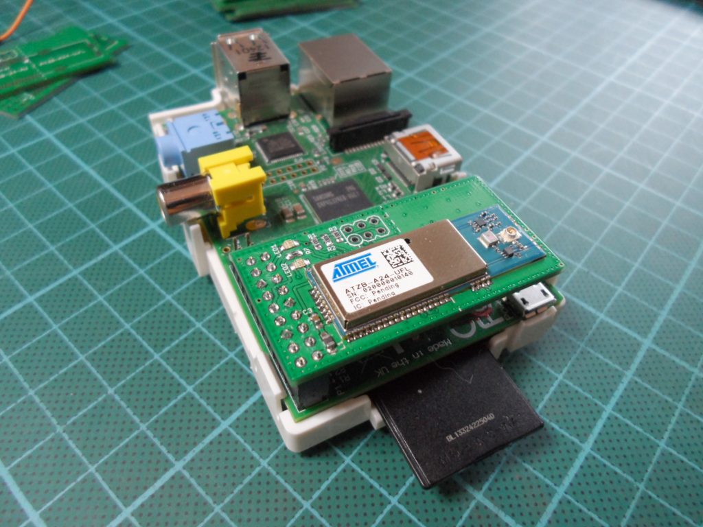
Shortly after creating the Contiki/Zigbit home automation proof of concept over Christmas, I laid out a 802.15.4 radio interface PCB for the Raspberry Pi and sent it off to Smart Prototyping for manufacture. With this interface and the 6lbr router software I can turn a Raspberry Pi into a nice small, self contained Ethernet to 802.15.4 border router, which will form the heart of my new home automation system.
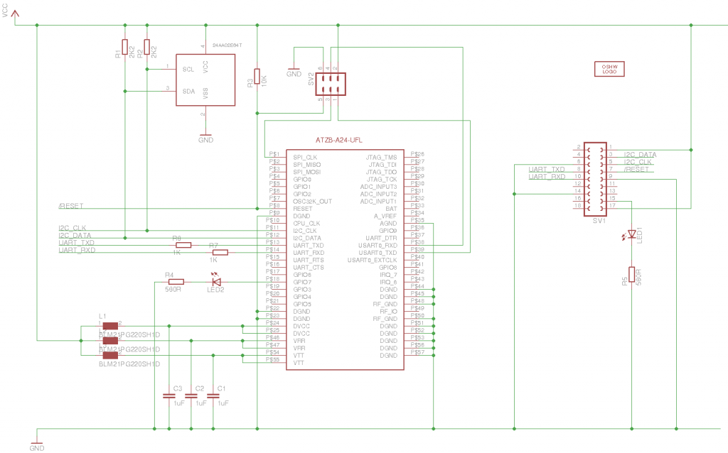
As the schematic above shows, the circuit is very simple. The Zigbit module is powered by the 3.3v supply on the Raspberry Pi’s GPIO header and it’s UART is connected to the Raspberry Pi’s UART via a pair of 1K resistors.
A Microchip 24AA02E64 EEPROM has been added and connected to the Zigbit module’s I2C pins. This is a 256 byte EEPROM that has the top 8 bytes permanently set to a unique IEEE assigned MAC address, and is used to set the Zigbit module’s address on the wireless network.
A pair of LEDs have also been added, one controlled by the Raspberry Pi and one controlled by the Zigbit module.
The Zigbit module’s reset pin has been connected to one of the GPIO pins with a 10K pull up so that the Raspberry Pi can reset it.
Finally a set of decoupling capacitors and ferrite beads have been added as recommended by the Zigbit module’s datasheet. Also recommended by the datasheet are the string of via’s that surround the PCB, apparently they stop the edge of the board acting as a microwave antenna.
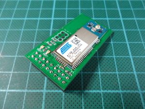
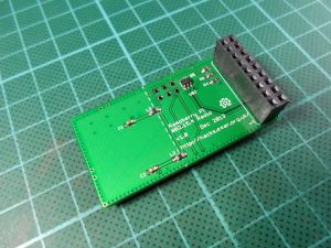
The board has been designed to take either a ATZB-A24-UFL amplified module with external antenna connector (as shown in the photos here), or a ATZB-24-A2 unamplified module with on board chip antennas. When the unamplified module is used, the board can be cut in half along the dotted line to remove the ground plane from under the antennas.
Even though the Zigbit module’s pads have a 1mm pitch with only 0.2mm gaps between them, once a couple of corners have been tacked down, they’re surprisingly easy to hand solder, as a small soldering iron tip sits nicely in the notches, which hold it steady and mean you don’t need to have such a steady hand.
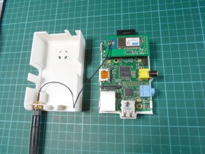
I added the connection between the Raspberry Pi’s GPIO header and the Zigbit module’s reset pin because with the proof of concept version, I’d found that if the 6lbr border router was started after the radio module was powered up, it was unable to obtain the radio module’s MAC address. So I wanted to ensure that the radio could be restarted after starting the router, just in case the problem couldn’t be solved in software. However, after trying the new board, I discovered that after the 6lbr router was started, the reset pin stopped working.
I couldn’t understand how software running on the Raspberry Pi could break something so fundamental as the hardware reset of the ATmega chip in the Zigbit module, especially when its only connection to it was via the UART. Eventually, after a lot of debugging and luckily stumbling on a helpful forum post, I was able to work out what was happening…
It turns out that in more modern AVR microcontrollers, when the watchdog triggers and they reset, the watchdog remains enabled. Not only does it remain enabled, but it has the shortest possible timeout, a timeout too short for Contiki to finish booting. So once the watchdog triggered once, the microcontroller went into an infinite reset loop, never managing to finish booting Contiki again.
Why did this only happen after the 6lbr router was started? Because the first thing the router does is send a reset command to the SLIP radio software running on the Zigbit module, which implemented the reset by going into an infinite loop and triggering the watchdog!
To get around this, I’ve added a call to watchdog_init() as the very first line of main() in contiki-avr-zigbit-main.c, which disables the watchdog before it can fire again.
And with that, the first element of my new home automation system seems to be working perfectly.
Files
Browse: repo
Recent Comments