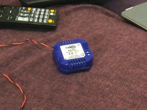
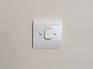
Most of the lights in my house are incandescent bulbs controlled by RAKO PILL dimmers. These dimmers fit into the back-box behind the light switch and have the advantage of keeping a normal looking light switch in addition to adding dimming and wireless control, which makes for a very invisible system, which I like. The actual light switch is swapped out for a momentary switch instead of the traditional rocker and becomes press once for on, press again for off, press and hold to dim up, press and hold again to dim down.
My kitchen light however is a flourescent tube. I wanted to be able to control this in exactly the same way as the other lights in the house, including keeping the normal looking light switch. After a bit of research I found that this is possible by using a DALI electronic ballast in combination with a controller from Tridonic (DALI GC-A) that fits in the light switch back-box in exactly the same way as the DALI PILL does for the incandescent lights, and also has exactly the same press on, press off, press and hold to dim control method.
The DALI control system operates on a shared bus and can have multiple lights and multiple controllers on the same bus and RAKO make a RAKO wireless to DALI bridge, so it looked like I could combine a DALI balast and switch controller from Tridonic with the RAKO DALI bridge and get seamless and invisible control of my flourescent light. I was almost right, but once I’d bought all the components and set it all up on the bench for a test there was one small flaw…
The RAKO DALI bridge appears to be designed with the assumption that there will be no other controllers on the bus, when you set the light level to 75% via RAKO, the bridge broadcasts a “go to 75%” command, but then it does it again, and again, and again… many times per second, forever. Now if you press the light switch to turn the light off, it sends a “turn off” command to the ballast and then a fraction of a second later the RAKO DALI bridge sends a “go to 75%” command and turns it back on!
Having spent a crazy amount of money on this setup, I didn’t want to give up on it and instead came up with the idea of creating a device to filter out the duplicate commands that the RAKO DALI bridge sends. So if the bridge sends 75%, 75%, 75%…80%, 80%, 80%…100% what would actually get through to the shared DALI bus would be 75%, 80%, 100%.
The DALI Bus
The DALI bus operates on just two wires, using the same pair of wires to provide power to the controllers and for signalling. A current limiting power supply puts a voltage on the bus, usually around 16V but apparently anywhere from about 10V to 22V is within spec. The current is limited to 250mA. The devices communicate using a manchester encoded serial protocol which is transmitted on the bus by short circuiting it, hence the need for the current limit. Anything above 9.5V is considered a “1” and anything below 4.5V is considered a “0”.
Controllers send 16 bit messages enclosed between a single start bit and two stop bits. The first 8 bits are an address and the second 8 bits are a command.
Slaves (ballasts, etc.) can reply with an 8 bit response, also enclosed between a single start bit and two stop bits.
The filter for the RAKO bridge only needs to be one way, the bridge only ever sends “go to x%” messages and will never try querying a slave. The actual format of the command messages can also mostly be ignored, the filter only needs to be able to compare one message to another to see if they’re the same.
The Prototype
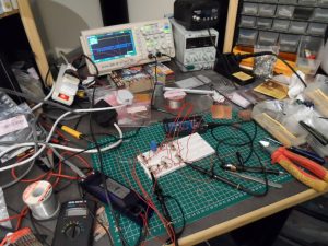
I created a prototype on a breadboard, using an Arduino for the processing. The cicuit is fairly simple, two wires come in from the DALI bus on the RAKO side and as there is no defined polarity on the DALI bus they go into a rectifier bridge. The output of the rectifier goes to a 5V regulator and a large capacitor that will continue to provide power while the bus is short-circuited during message transfer. There’s also a diode to stop the capacitor sending power back to the bus.
A voltage comparator is used to compare the bus voltage with the reference voltage from the regulator to detect the logic “0” when the bus is short-circuited. The output of the comparator is fed to the Arduino.
The output of the Arduino is passed through an opto-isolator to keep the two DALI busses with their separate power supplies electrically isolated. The output of the isolator is used to control a MOSFET which short circuits the DALI bus on the output side to transmit messages. Finally the output is connected to the output bus via another rectifier bridge.
That’s essentially it. The rest is software to decide when to relay the signal from one side to the other.
The Firmware
The firmware is also fairly simple. It’s entirely interrupt driven and is logically divided into two halves, one for receiving and one for transmitting.
For the receive portion, the comparator is connected to the INT0 pin of the microcontroller so whenever there is a change in the logic level of the bus the INT0 interrupt handler is called. When this interrupt fires, if we’re not already in the middle of receiving a message then the receive timer is started. The receive timer serves two purposes, the first is to measure the time between transitions so that we ignore the level for the first half of the manchester encoded bit and only use the level from the second half. The second purpose is to act as a timeout for the receive process. Rather than actually counting the bits of the message and looking for the stop bits we just wait for the line to be idle for a while to indicate that we now have the full message.
When the receive timer overflows, signalling that the bus is idle and the message reception is complete, the timer1 overflow interrupt handler is called which stops the receive timer and compares the messages against the last received message. If the current message is different then it calls transmit() to pass the message to the output.
The transmit() function copies the message, reversing the order of the bits ready for transmission onto the wire, resets the transmit clock counter and starts the transmit timer. The transmit timer fires twice per bit. Whenever it fires the low data bit is XOR’d with the low bit of the transmit clock counter to manchester encode it and the output pin is turned on or off accordingly. Every other time the transmit timer fires the data is shifted right to lose the lowest bit and move on to the next one. Once there are no more bits left to transmit then the transmit timer is turned back off.
DALI Filter Version 1
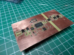
With the prototype working it was time to create the real thing. I made a few small modifications to the design, the Arduino was swapped out for an ATTINY861 and I added a zener diode and polyfuse to each side in an attempt to protect the circuit from accidental connection to 240V mains power.
After a quick test on the bench everything seemed to be working so I installed it all into the back of the flourescent light fitting and powered it up, but… it didn’t work!
The only difference between when I was testing on the bench and the real installation was the power supply. When I was testing on the bench I was using my bench supply with a low current limit. In the real installation I was using a Tridonic DALI power supply with a full 250mA limit. It turns out that my circuit isn’t strong enough to pull the bus voltage down below 5V when there is 250mA available.
DALI Filter Version 2
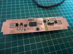
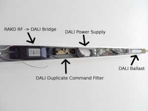
I wasn’t entirely sure whether version 1 wasn’t able to pull the bus voltage down because the MOSFET wasn’t suitable or if it was just because the output side loses power as it short circuits itself, though I suspect the latter. To play safe I fixed both potential issues, I added a capacitor and diode to keep power available during the short curcuiting and I beefed up the MOSFET.
After making and populating a new PCB and another quick test on the bench, this time with a higher current limit, it was all installed in the flourescent light again. This time… success! I can now control the kitchen light via the light switch and wirelessly via RAKO automation and they don’t interfere with each other.
After a few months of use only one small flaw has surfaced, if I turn the light on via RAKO to 100% then later turn it off via the wall switch, then later still try to turn it on to 100% via RAKO again, nothing happens because the RAKO command is blocked as it’s identical to the last one. It’s not too much of a problem though, I just have to turn it to 98% then back to 100% to get it to come on, which I can live with.
Files
Browse: repo
Can you please get in touch with me?
regards
Hi Yigit, if you want to talk via email my address is the same as this site’s domain, just replace the first dot with an at, so it’s hacks at instead of hacks dot.