VGA Controller – Timing
- VGA Timing Board
- Horizontal Sync
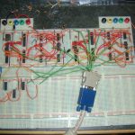
Horizontal timing on the left half of the board: A 25MHZ crystal clocks a 12bit ripple counter, counter output goes to 3 separate 4-to-16 decoders, a collection of AND gates and inverters switch a pair of flip-flops on and off at the right clock counts to produce the horizontal sync.
Vertical timing on the right half of the board, almost identical to the horizontal timing, just clocked by the horizontal sync rather than the crystal.
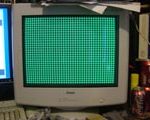
To test the timing a grid is drawn by turning on the green output, controlled by the vertical and horizontal count decoders. The (approximately) correct voltage is achieved by using a resistor and diode so that the green output voltage is one diode drop.
Read More →


Recent Comments