I’ve very rarely done any threading on my lathe. Changing the gears was always way too much of a pain, which meant I used a die whenever possible and left the gears permanently setup for feed. So after Youtube started recommending videos from Clough42’s series on his Electronic Lead Screw project, I was inspired to do something similar for my Lathe.
For anyone unfamiliar, a lathe usually has a chain of gears linking the spindle/chuck to the lead screw that drives the carriage backwards and forwards along the bed. The gears can be changed to alter how far the carriage moves for each rotation of the spindle. For example, to cut the thread on an M6 screw, the gears would be setup so that the carriage moves 1mm for each rotation.
On this lathe, changing the gears involves two spanners, an allen key, and digging through the big pile of gears to find the four that the cryptic chart says are required for the desired ratio. It takes a good five to ten minutes and gets your hands covered in oil and grease. An electronic lead screw replaces the chain of mechanical gears with an encoder that reads the spindle speed, a stepper motor or servo to turn the lead screw, and a controller to link the two together. Then the ratio can be changed instantly at the press of a button.
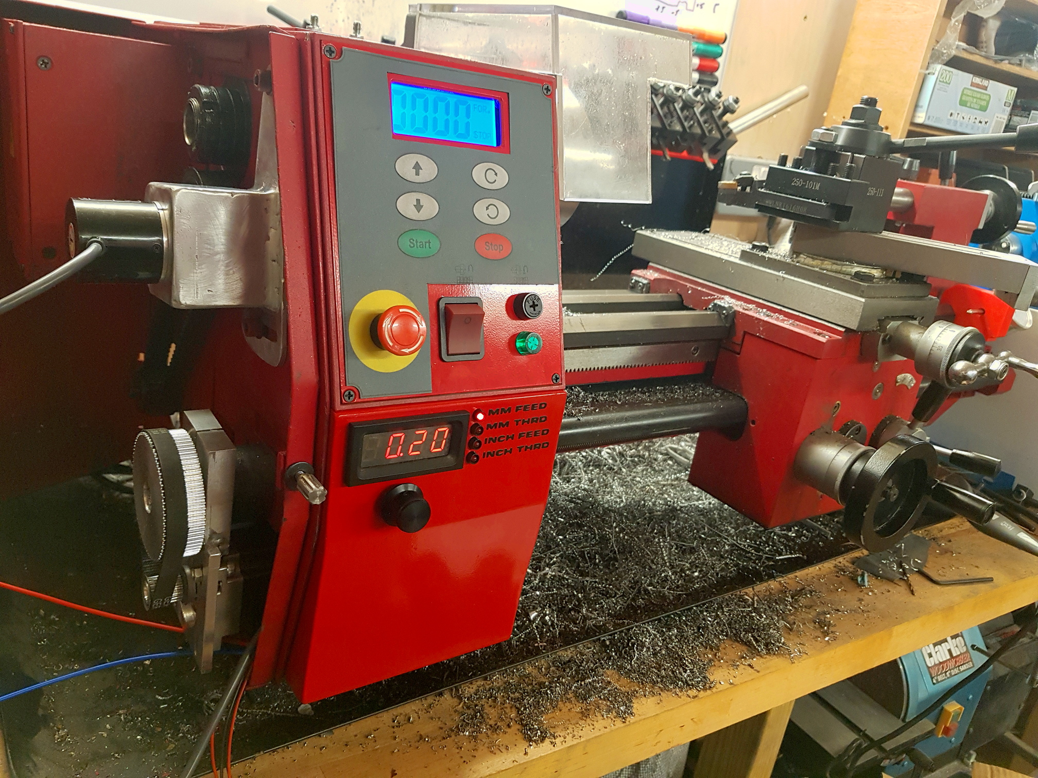
Rather than using Clough42’s implementation I wanted to create something more tailored to my lathe. As can be seen in the title image above, I’ve simplified the user interface to just the display and a single combined rotary encoder and button, and as the SC4 already has one, I’ve also eliminated the RPM display. After relocating the lathe’s power switch, fuse, and indicator lamp, to the main control panel, I’ve added the ELS controls in the space they used to occupy.
The Servo
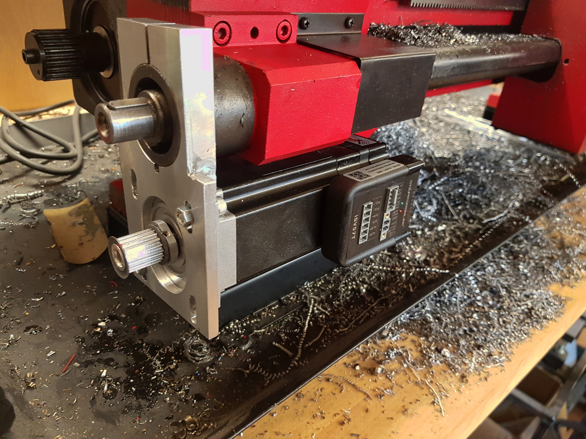 The first decision was how to drive the lead screw. For this I’ve chosen to use the same servo as Clough42. The iSV57T-180S from Stepper Online, which is a NEMA 23 size motor capable of delivering good torque up to 3000RPM. See his video for more detail.
I’ve chosen this motor partly because he’s already proven it suitable for the purpose, and partly because it simplifies the install by not requiring a separate controller. It does need a separate power supply to feed it 36V, but after that it can be driven by a logic level pulse train directly from the micro-controller.
As shown in the photo, I’ve been able to tuck this away under the lead screw. It’s held in place by a custom mounting plate that grabs hold of the case around the end of the lead screw, right where the change gear banjo bracket used to be. I’m then driving the lead screw through a 15mm wide, 3mm pitch HTD timing belt. The motor has a 18 tooth pulley (pretty much the smallest that can be drilled out to fit the shaft) and the lead screw has a 72 tooth pulley, giving a 4:1 drive ratio and a nice boost to the torque on the lead screw.
The Spindle Encoder
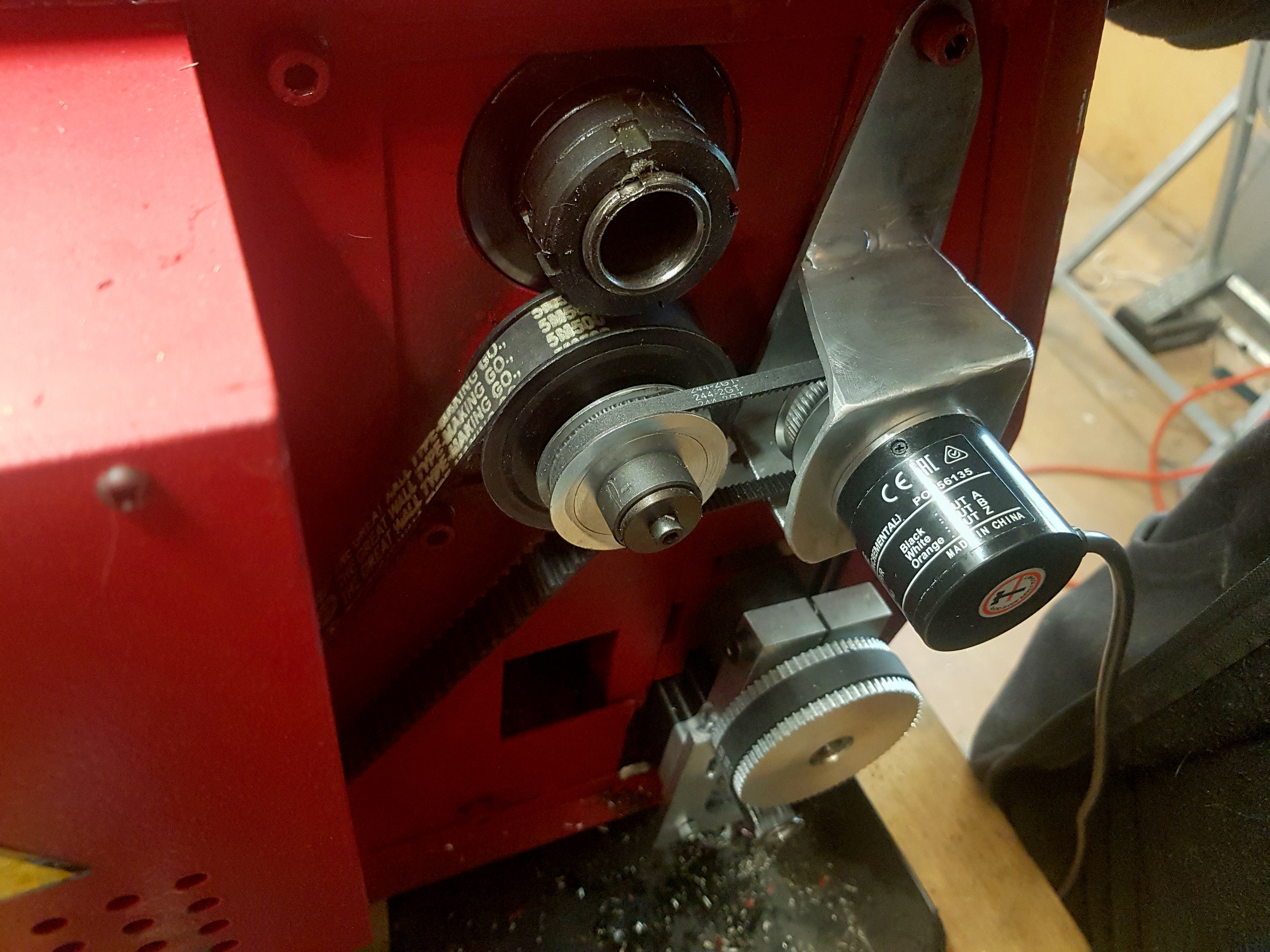 The next piece of the puzzle was the spindle encoder. Once again I’m using the same one as Clough42, a 1024 pulse Omron E6B2-CWZ6C. Or more precisely, SparkFun’s knock off, the COM-11102, which has the advantage of costing 5x less than the genuine Omron unit.
In retrospect, a 1000 pulse per revolution version would probably make more sense, then the ratio between encoder pulses and servo pulses could be a nice whole number.
The encoder is mounted with another custom bracket. This time reusing a couple of mounting bolts that hold the drive enclosure to the main casting. You can’t see it in the photo, but there’s a slot in the bracket where the bottom bolt goes through to allow it to swing side to side to take up slack in the belt. This time I’m using a GT2 belt and a pair of 60 tooth pulleys.
Enclosure Modifications
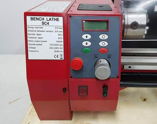 The image on the right shows the original configuration of the SC4 control panel.
There’s a big silver knob wasting space in the main panel. It’s purpose is to disengage the spindle from the drive motor when using a milling attachment that I don’t have.
Then the main power switch, fuse, and indicator lamp are in the lower section taking up space that would be perfect for the new ELS controls.
Finally, the lower panel doesn’t go low enough to cover the servo I’ve just added, in fact the bottom of it wants to cut right through the middle of the servo.
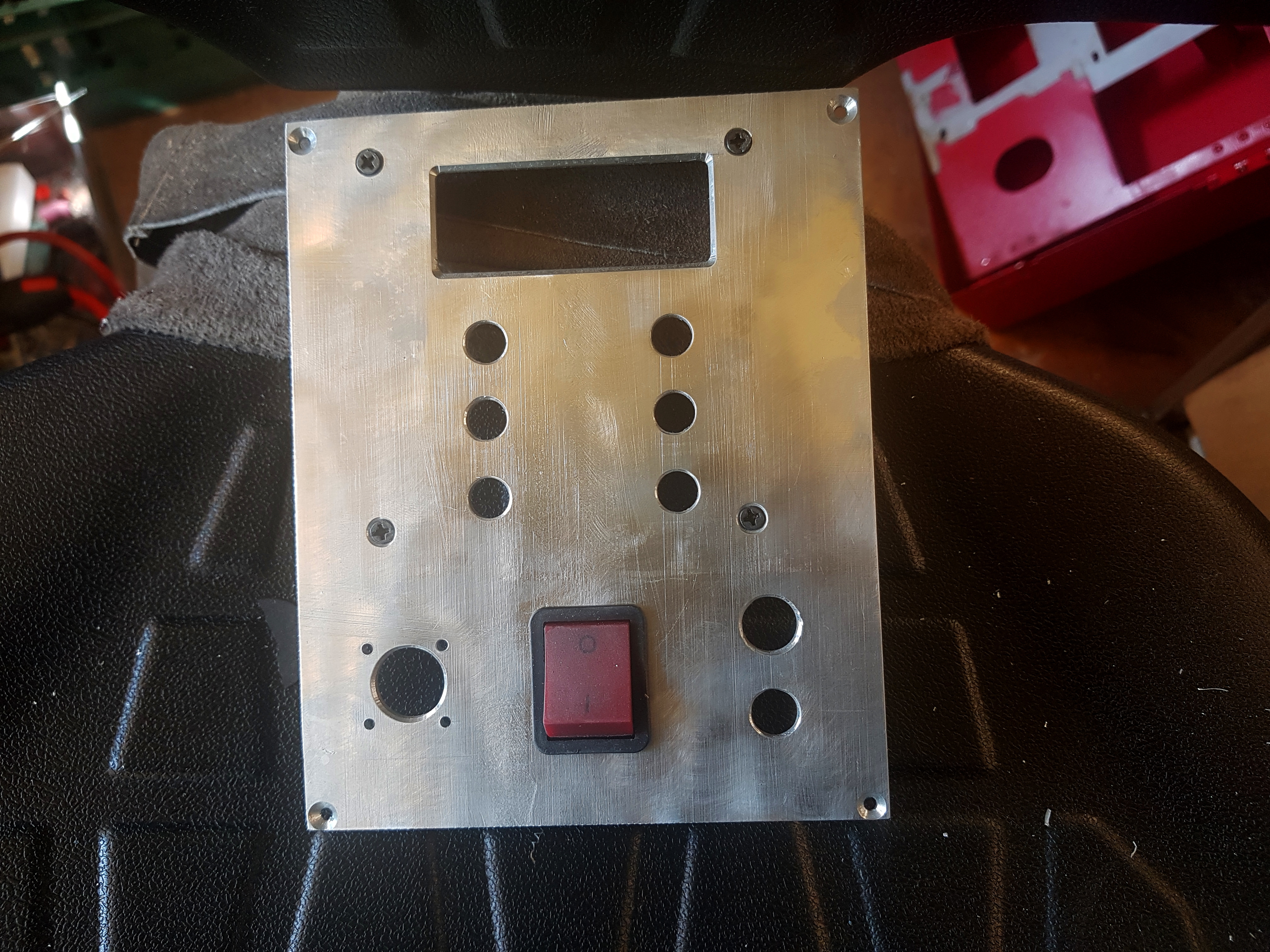
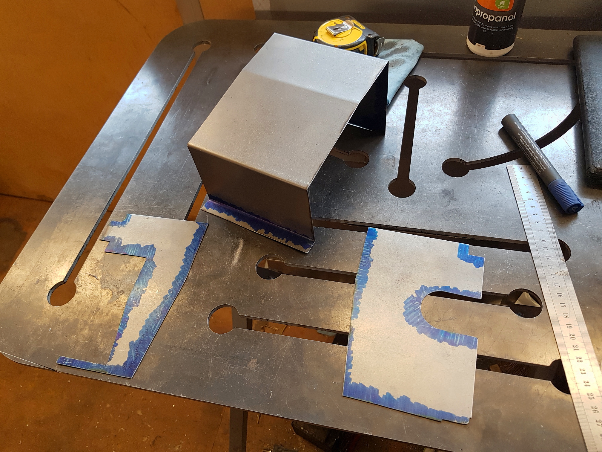
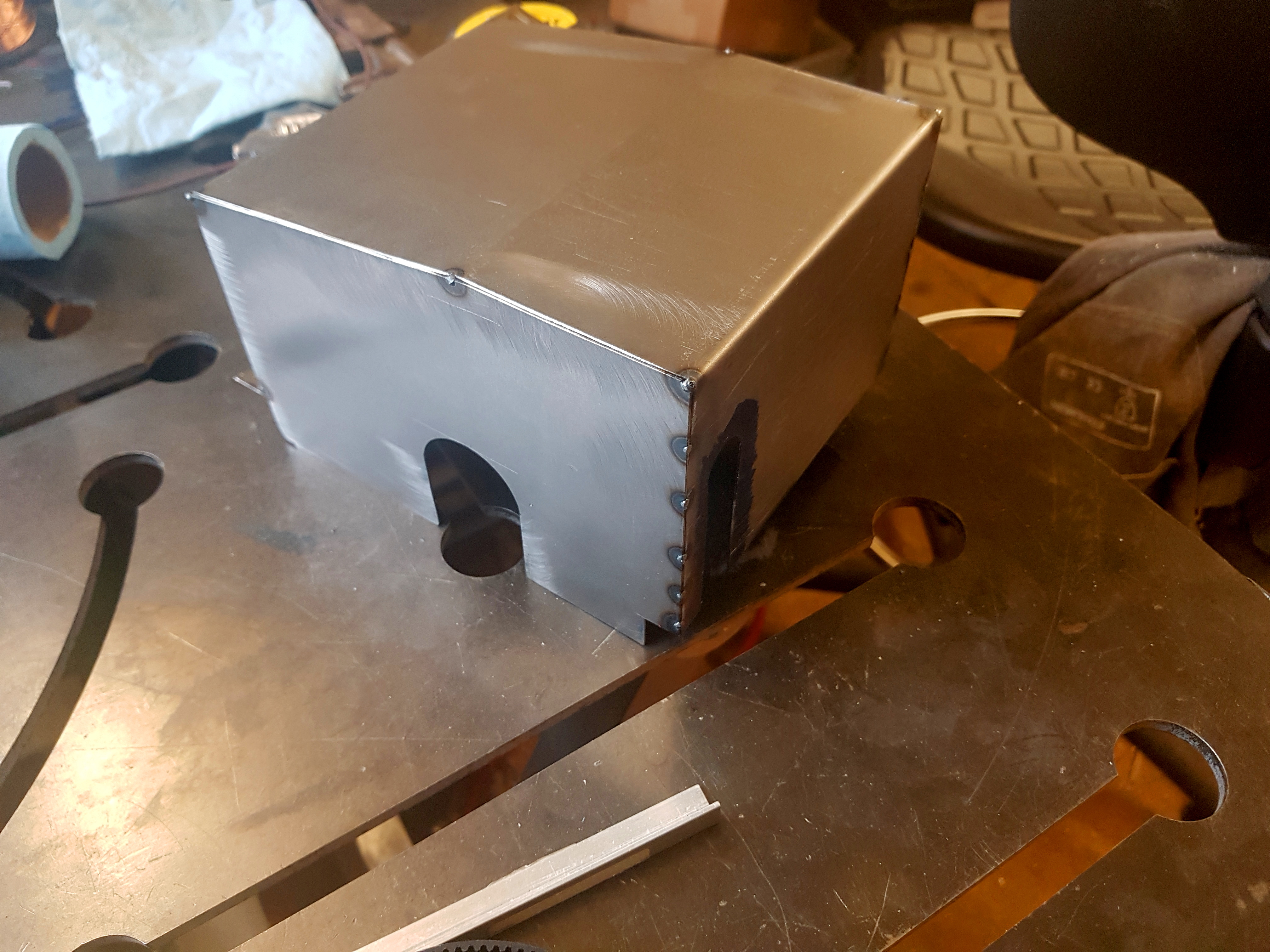
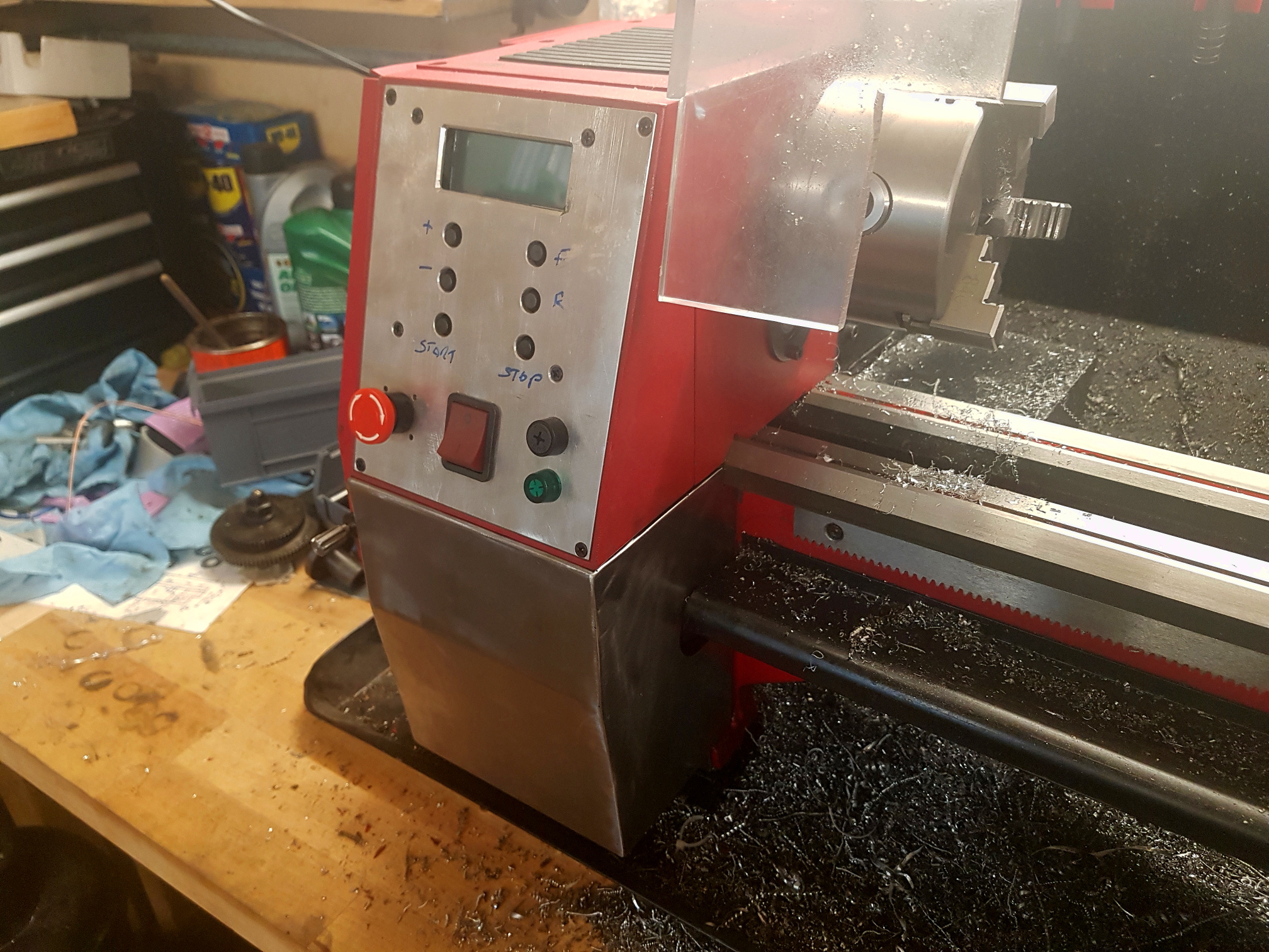
To make this work, I’ve deleted the silver spindle drive knob and relocated the power switch, fuse and indicator to the space it used to occupy in the main control panel. These are mounted in an aluminium panel that I’ve cut to replace the original plastic one. I’ve then folded a new, slightly larger lower enclosure from sheet steel, welded the pieces together and powder coated everything red.
The Controller
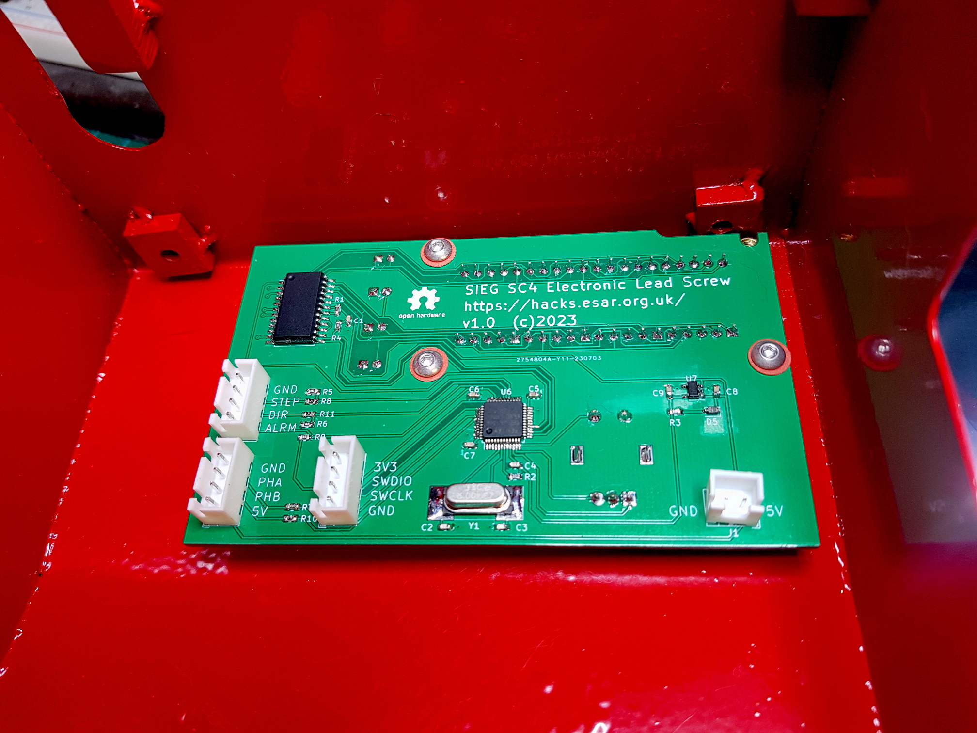 I’ve based the controller on the STM32F103C6 from the Blue Pill development boards, and the MAX7219 display controller. There’s very little else to it… four 7-segment LEDs to display the selected value, four LEDs to show the chosen units, an Alps rotary encoder / button for user input, a 3.3V regulator, and a handful of capacitors and resistors.
Everything is controlled through the one knob. By default it does nothing, so you can’t accidentally change anything. Click it once and the digits will start flashing and you can scroll up and down through the pre-defined feed rates, scrolling clockwise goes up, scrolling anti-clockwise goes down, keep going down past zero into negative numbers and we’re in reverse. Clicking again will lock in the value, otherwise after a 5 second timeout it’ll return to the previous setting.
Double clicking will set the units LED flashing and you can scroll up and down through the four available units… mm feed, mm threading, inch feed (in thou), inch threading (in TPI). Again a change is locked in by a click, but this time after locking in the units change, the digits will start flashing and the value can be changed immediately without needing to click.
If a fault occurs… the controller can’t send pulses to the servo fast enough, or the servo raises a position error… the servo will be halted and the display will flash an error code. This can be cleared with a quadruple click (just to make sure you can’t do it by accident)
The Firmware
As usual when I write code for a microcontroller, almost everything ends up being done with one of the hardware timers. This time I’m using three of them, plus the one for the system clock. Timer2 is being used as a quadrature decoder for the user input encoder, Timer3 is the quadrature decoder for the spindle encoder, and Timer1 is used to send pulse trains to the servo.
There are two ‘loops’ running in the code. The important one that drives the servo in the right ratio to the spindle encoder input is driven by the system clock interrupt. It runs once every microsecond and takes the latest spindle encoder position, calculates the desired servo position from it, and decides how many pulses are required to get the servo to the target position. It then sets the repeat count on Timer1 (which is configured in one-pulse mode) so that the hardware sends the required number of pulses without the CPU needing to get involved again until the next timer interrupt.
In parallel the user interface loop runs once every 10 milliseconds (subject to the interrupt driven loop not wanting the CPU), and checks if there is any user input and drives the display and updates the configuration variables accordingly.
The Files
All of the code and the Kicad files for the PCB can be found in the github repo.
A 3D model of the cover I made for the terminals on the Meanwell PSU I’m using (LRS-350-36) can be found in my Onshape account here. It fits PG7 and PG9 cable glands.
Hey!
I just replaced my old lathe with a Sieg SC4 and, after getting my hands covered in change gear filth for the tenth time, I’m considering copying your project. Are you still happy with how it works? Have you made any improvements since you posted this blog?
Cheers,
Travis.
Hi Travis, yeah, still happy with it. It easily the best mod I’ve made to this lathe.
Even when not threading, it’s so useful being able to instantly switch between speeds for roughing and finishing cuts.
I’ve not changed anything since the initial version. The only thing I want to do is change the default feed rate to one step lower on power on, but it’s not bothered me enough to get the laptop out and reprogram it.
Good to hear! I’ve based my controller solution on your code, but running on an ESP32-C6 with an LCD. My servo should arrive today. The pulleys, belts and encoder should follow soon after. I wasn’t sure how long the belt needed to be, so I ordered a range of sizes, hopefully one of them is suitable.
Cheers,
Travis.
Good luck with the build.
I just checked my Amazon and Ebay order history to see if I could tell you the belt size I used, but it looks like it must have taken me several attempts to get the right one. Seems I ordered a 252mm long one, then 285mm and 288mm, and finally a 264mm and 267mm. I’m guessing I used one of the last pair, but couldn’t guarantee it 🙂
Thanks for the info! I know for a fact the belts I ordered won’t be suitable, as I seem to have somehow ordered belts with fewer teeth than the biggest pulley. (??)
I think I’ll just test fit the setup, measure the belt path with some string, and then order the belts.
A quick question about the encoder: Did you end up changing the ratio for the spindle encoder? In your blog post you mentioned you were using a pair of 60-tooth pulleys to link the spindle and the encoder, however the code has a 4096 constant for the encoder counts-per-rev.
I’ve got a testbench set up with a 1000 cpm encoder and the iSV57T and I’m having issues with rounding errors from the ratio calculations. I’m wondering if you overcame the same issue by changing the ratio on the encoder.
Cheers,
Travis.
Hi, I’m still using the 1024 step encoder and the 60 tooth pulleys, so I have a 1.024 ratio between encoder and motor.
How large are the errors that you’re seeing? What lead screw ratio are you testing with?
If I had switched to the 1000 count encoder then I would have had a 1:1 ratio between encoder and motor, an integer thread pitch ratio of 2 and an integer drive ratio of 4, so the total ratio would be an integer for metric threading, and there I’d expect no error at all. For imperial threading I would have some rounding error, but it should be small enough to not have any practical effect. Especially as it’s not cumulative with the calculation being redone from the total encoder count on every update.
I’ve worked out my issue; I think it was down to interrupt contention leading to missing encoder edges. I’ve tweaked some timers/rates and things seem to be working better. I’ve posted a youtube video of my progress here: https://youtu.be/v_Xlgs-Bak4
Excellent! Looking good so far.
It’s funny seeing the size of those belts 🙂
Hopefully you’ll have more luck with the next set, and won’t need a third like I did.