 After getting the Vive position sensors working in my last post, I’ve been working on the next piece of the puzzle… how to send all of the positions back to the controller.
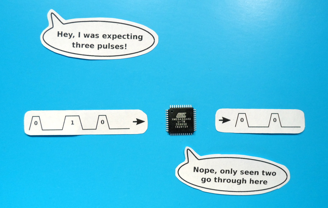
I’ll have a collection of position sensors linked together in a chain, and I’ll need to send the positions back along the chain to the controller, using as few wires as possible. This is really similar to sending colour information out to a chain of LEDs, just in the opposite direction, so I thought I might be able to use the same single wire signalling system.
Unfortunately, due to a quirk of the pulse width capture mode of the AVR Xmega’s timers, this didn’t work out.
The Plan
The plan was for each sensor to send out its position 30 times per second. Each sensor would send its position to the next one down the chain, which would prepend its own position and relay the combined message to the next, and so on, all the way back to the controller. The sensors would automatically synchronise their transmissions by slightly changing the delay between updates, depending on whether a sensor had received any data in the past or not.
If a sensor had received data then it would either transmit again when it next received incoming data, or when 50 milliseconds had elapsed since the last time it had received data. If a sensor had not received data then it would only wait 33 milliseconds before transmitting, so the sensor at the end of the chain would quickly end up being the one that initiated the sending process for the whole chain.
The end result would be that every 33 milliseconds the controller would receive one contiguous block of data containing the position of all of the sensors.
This seemed like it should be fairly straightforward. Within each sensor’s micro-controller I could have a buffer holding its current position. Then when it started receiving data, it would also start to send data, shifting the data out of the buffer and replacing it with the received data. Then with the buffer acting as a shift register, it would relay all of the received position information after it had sent its own. Once it stopped receiving data it would then reload the buffer with its updated position, ready to start again when it next received incoming data.
WS2812 Protocol

WS2812 Protocol Timing
The only real difference between the protocol used by the LED strips and the protocol that I’d use for the position data would be the message length. Each message sent to the LEDs is 24 bits long, containing 8 bits each for red, green and blue. My position messages would be 64 bits long, each consisting of four 16 bit tick counts, corresponding to the four laser line sweeps from the Vive lighthouses.
To implement my planned relay system I needed the micro-controller to be able to measure the widths of the incoming pulses, convert them to 1’s and 0’s, write them to the buffer in memory, and then simultaneously send a train of pulses out of the output. With each pulse being only 1.25uS wide, and with a 32MHz system clock, I’d only be able to execute a maximum of 40 instructions per pulse, so this all needed to happen in the hardware peripherals, with as little involvement from the CPU as possible, especially as I already had plenty of other things for the micro-controller to be doing.
Implementing In An Xmega

Xmega Implementation
This DMA controller can be configured to automatically move data between the peripherals and memory. So I could have one channel listening for new pulse width measurements from the timer, and automatically moving these into a buffer. Then I could have another channel simultaneously listening to the USART’s buffer empty signal and automatically moving data from a buffer to the USART in response. Then the only involvement that the CPU would need to have would be to translate the pulse widths in the input buffer to the appropriate data in the output buffer.
The block diagram above shows what this looks like inside the Xmega32A4U’s that I’m playing with.
- Timer TCC0 is set to pulse width capture mode, running at the full 32MHz system clock speed. A new measurement becoming available as each falling edge occurs
- DMA channels 0 and 1 are chained together in double buffer mode, each taking turns to read 64 8-bit pulse widths from the timer into a receive buffer.
- On completion of each DMA transfer, an interrupt handler reads the pulse widths and translates them into the next available send buffer.
- Meanwhile, DMA channel 2 copies the contents of a filled send buffer to the USART, which is set in SPI master mode and clocked at 3.2MHz, turning each set of four bits from the buffer into 1 bit of output
- When each send DMA transfer completes, another interrupt handler checks if another buffer has been filled, and if one has, it kicks DMA channel 2 into action again
It Works… Sometimes…
Success
Failure
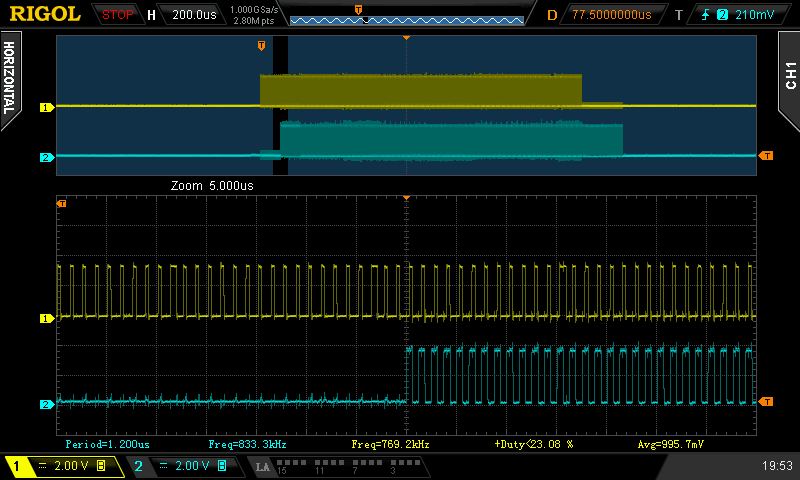
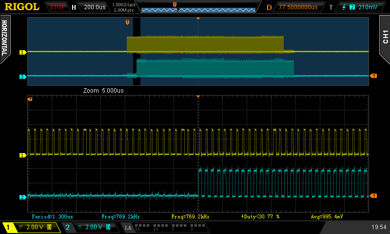
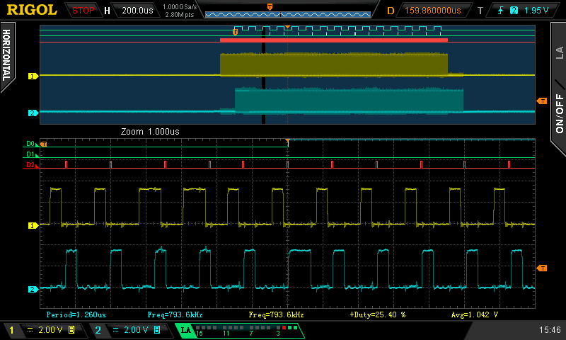
Looking at the input and output on the ‘scope I could see that the output started shortly after the input, and zooming in I could see that it was correctly sending its own data before relaying the incoming data. However, it wasn’t long before I spotted something weird. The length of the output data kept changing. A lot of the time it wasn’t sending the last 64 bits of data, so the output was the same length as the input rather than being one 64 bit message longer.
At first I just assumed that something was going wrong with the way that I was triggering the sending DMA channel, maybe the timing was occasionally a bit off and it didn’t see the last buffer in time? It didn’t take long to rule this out though. After adding a pin toggle to the transfer complete interrupt handler for the receive DMA channels, I was able to see that the last DMA transfer from the timer never completed.
There’s really only one thing that can stop the DMA channel completing a transfer, and that’s if it doesn’t get enough triggers. Could some bits have been missed?
The incoming data was coming from another micro-controller that was programmed as a test data source. It was sending out a burst of 16 messages every second, and the content of the messages were incrementing numbers, message one was {1, 1, 1, 1}, message two was {2, 2, 2, 2}, and so on. If it was losing bits then I should be able to see it in the received data.
Lost Bits?
I updated the function that was decoding the pulse widths and got it to log the received data to the serial port. This showed that it was sometimes receiving the wrong data, and those times coincided with the last DMA transfer not completing. Here’s an example of what it received:
msg 0: 0001 0001 0001 0001
msg 1: 0002 0002 0002 0002
msg 2: 0002 0003 0003 0003 ***
msg 3: 0008 0008 0008 0008 ***
msg 4: 000a 000a 000a 000a ***
msg 5: 0008 000c 000c 000c ***
msg 6: 001c 001c 001c 001c ***
...
Due to the byte ordering, it’s not immediately obvious, but this shows that two bits were lost while receiving this burst of messages: the last bit of message 2, and the last bit of message 5, both of which should have been 1’s.
In binary, this is what the received data was supposed to look like, from the last byte of message 2 to the second byte of message 3. The arrow points to the lost bit:
  msg 2 |     msg 3
--------+-----------------
00000011 00000000 00000100
       ^
The lost bit meant that the data that was actually received was:
  msg 2 |     msg 3
--------+-----------------
00000010 00000000 00001000
That confirmed that incoming bits had been missed, but where had they been lost?
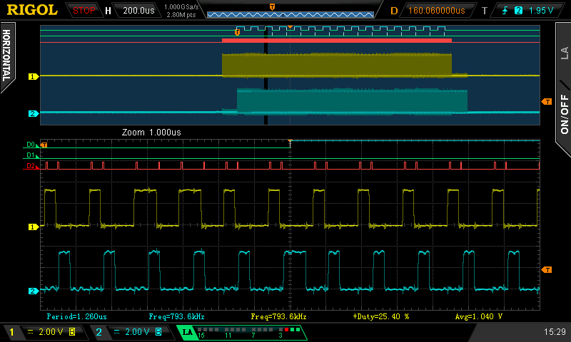
Pin Event (red trace)
CCA Event (red trace)
Next I routed the event from the timer’s capture channel A to the debug pin, and this was also fine. The timer was generating a capture event for every pulse. So that appeared to only leave the DMA controller as the culprit, but how could the DMA controller lose bits?
Maybe the DMA controller didn’t get all of the events? If that was the case then it wouldn’t read the value from the timer and the timer should flag an overflow event. I added code to check for this, but no overflow was ever flagged, so now it seemed that the DMA controller was reading all of the bits, just not writing all of them to the buffer. Now I was confused! How could it lose a bit somewhere deep inside the DMA controller?
I decided that it would be a good idea to simplify things a bit, so the next thing I did was disable the transmit half of the code by never triggering DMA channel 2. Now I only had the receive code operating, and strangely the problem disappeared. Now I was successfully receiving all of the bits, all of the time.
If disabling the transmit code fixed the problem, what about adjusting its timing a bit? The send and receive DMA channels both needed access to memory at around the same time, so after re-enabling the transmit code, I tweaked it to delay triggering of DMA channel 2 by a few clock cycles. This also fixed the problem, though not 100% of the time. Now it received all of the bits for most of the message bursts, but it still occasionally failed.
In contradiction to the previous evidence, this looked like more of a classic resource contention issue, with one of the DMA controllers starving the other of access to the bus. But there should be plenty of time for them both to get access, after reading each capturing pulse width, it had 40 cycles to get back and collect the next, and each one was only one byte. In fact it should be able to occasionally go 80 clock cycles as the capture registers are double buffered.
But of course, if it’s failing to read any of the capture values the timer should flag an error, and we’ve seen that it hasn’t.
Analysing Timer Behaviour
I was now asking myself “Am I really not getting timer overflow errors?”. Could I be doing something wrong? Did I need to do some configuration before the timer would flag the errors?
To answer, I stripped away all of the code and wrote a simple test program that would purposefully generate timer overflows to see how the timer behaved. I set the timer to capture on event channel 0 and then manually wrote rising and falling edges to that channel, checking and logging the capture and error flags after each change.
Here’s what happened when the timer was in pulse width capture mode (with commentary in brackets):
PW mode
=========
Flags:             ( Flags start empty                     )
rise               ( Send rising edge to timer input       )
Flags:
fall               ( Send falling edge to timer input      )
Flags: CCAIF       ( Capture channel A flags data ready    )
rise               ( Send rising edge to timer input       )
Flags:             ( Where did the data go?                )
fall               ( Send falling edge to timer input      )
Flags: CCAIF       ( New data available                    )
rise               ( Send rising edge to timer input       )
Flags:             ( and the data's gone again!            )
fall
Flags: CCAIF       ( note: no overflows getting flagged    )
rise
Flags:
fall
Flags: CCAIF
restart            ( send a restart command to timer       )
Flags:             ( where did the data go?                )
restart
Flags:
Now that’s not what I expected to see! In pulse width capture mode the timer is supposed to reset to zero on each rising edge, then count up until the falling edge occurs, storing the count on the falling edge. However this test seemed to show that the reset did more than zero the count. It seemed to have totally reset the counter, losing the data.
For something to compare against, I re-ran the test with the counter in plain capture mode. In this mode it should keep counting continuously, storing the count on both rising and falling edges, and wrapping the count back to zero when it reaches the top. Here’s what that looked like (note the behaviour when sending reset commands to the timer at the end):
CAPT mode
=========
Flags:             ( Flags start empty                     )
rise               ( Send rising edge to timer input       )
Flags: CCAIF       ( Capture channel A flags data ready    )
fall               ( Send falling edge to timer input      )
Flags: CCAIF       ( All buffers now full, no overflow yet )
rise               ( Send another rising edge to the timer )
Flags: CCAIF ERRIF ( Overflow error flagged as expected    )
fall
Flags: CCAIF ERRIF ( More of the same...                   )
rise               ( ...we're not consuming...             )
Flags: CCAIF ERRIF ( ... so flags stay the same            )
fall
Flags: CCAIF ERRIF
rise
Flags: CCAIF ERRIF
fall
Flags: CCAIF ERRIF
restart            ( Send restart command to timer         )
Flags: CCAIF       ( Where did the error flag go?          )
restart            ( Send another reset command            )
Flags:             ( Where did the CCA flag go?            )
Now finally I got to see the error flag working, so it wasn’t just a misconfiguration. I also got a better view of what was happening around the resets. From this run it looked like the reset wasn’t doing a total reset, but it did seem to be consuming the data from the data register. The first reset consumed the data, clearing the error flag and moving the other captured data from the double buffer to the main register, so the capture flag was still set. Then the next reset consumed the data again, leaving the flags empty as there was no data in the double buffer this time.
Conclusion
From the results of those tests I think it’s obvious why I was losing bits. After reading the Xmega manual, I understood that the capture was double buffered and that I would have up to 80 clock cycles to come and collect samples, but in reality I actually only have the time between the falling edge at the end of one pulse and the rising edge of the next.
The worst case from the WS2812 specification means that I now only had 14 clock cycles (600nS – 150nS = 450nS), not 80. Plus, in reality the WS2812’s will accept an even smaller gap. For example, my HDMI Light project uses a 75% high time for 1’s, which would reduce the available time to a mere 10 clock cycles.
There’s just no way that the DMA controller can reliably collect the data within such a small time window. It has to contend with the other DMA channels and the CPU (which always wins) for bus access.
Additionally, the tests have shown that the error flag will never be set in pulse width capture mode, so there isn’t even any way to detect an overflow and try to recover.
It looks like it’s time for Plan B, though I’m not yet sure what that will be. Do I find a different micro-controller? Maybe an ARM? Or do I change protocol to something like SPI that wouldn’t need the pulse width mode of the timer, but would need an extra wire for the clock? Not sure…
Source Code
For what it’s worth, all the code can be found on github here
Great bit of work – thanks very helpful. Shame the documentation for the DMA is not more detailed on timing matters (such as how quickly the destination address is reloaded).