One problem with my HDMI Ambilight project is that it can’t handle encrypted content, or more accurately, it can only handle encrypted content if I spend a lot of money and get an HDCP license, which would then allow me to buy the version of the ADV7611 chip that has built-in HDCP keys. While this doesn’t cause me much of a problem as I tend to watch almost everything via MythTV, with the TV on the HDMI port and the HDMI Light on the DVI port, it would be nice to be able to use an HDMI splitter between my AV receiver and TV instead, and have it still work on the odd occasion when I watch a BluRay directly.
Luckily, my post announcing HDMI Light version 2 was featured on Hackaday, where a couple of people pointed out that it’s actually quite easy to disable the encryption in some HDMI splitters, effectively turning them into HDCP strippers. Even more helpfully, RoyTheReaper described exactly how to disable the encryption in an HDMI splitter I had lying around in my junk box.
While his method works perfectly as far as disabling the decryption is concerned, it has the side effect of also disabling all of the nice little extras that come with HDMI like automatic input switching and controlling the AV receiver volume from the TV remote. What I needed to do was find a way to let the microcontroller in the splitter continue to do all the other things it does while stopping it from enabling encryption.
The Basic Hack

Basic Hack Working
As it turns out, the splitter’s outputs are unencrypted by default regardless of whether the incoming signal is encrypted or not, and all that’s needed to disable encryption of the splitter’s output is to stop the microcontroller from talking to the main splitter chip. This can be achieved via any of a number of different methods, such as:
- Put the microcontroller into boot loader mode by pulling pin 16 up to 3.3V before powering up the rest of the board.
- Remove the 0 Ohm resistors that connect the microcontroller to the splitter’s I2C bus, or if they’re not present, just cut the traces.
- Completely remove the microcontroller from the board.
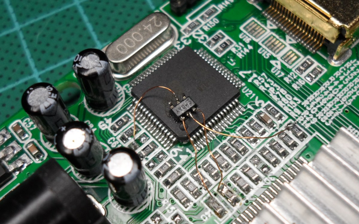
The photo above shows the result of trying the first of these methods, I’ve got my bench supply applying 3.3V to pin 16 of the microcontroller, the input signal is the encrypted output of my Bluray player and both the TV and HDMI Light are receiving an unencrypted version… Success!
Unfortunately though, the microcontroller isn’t just there to turn on the encryption, so while this works perfectly for eliminating the encryption, it breaks a whole lot of other stuff:
- The volume control on the TV remote no longer controls the AV Receiver volume
- When the TV is the content source, such as running its built in iPlayer app, the AV Receiver no longer switches input to the TV
- Even after manually switching the input, the sound from the TV doesn’t get to the AV Receiver, it should be sent via the Audio Return Channel (ARC)
- Every time I press play on the Bluray player, the TV switches to the HDMI-1 input, instead of staying on HDMI-2 where it will actually receive a signal
- The Bluray player now refuses to play any 3D content as it doesn’t think the TV is 3D capable
Finding A More Targeted Hack

Experimenting With I2C Overrides
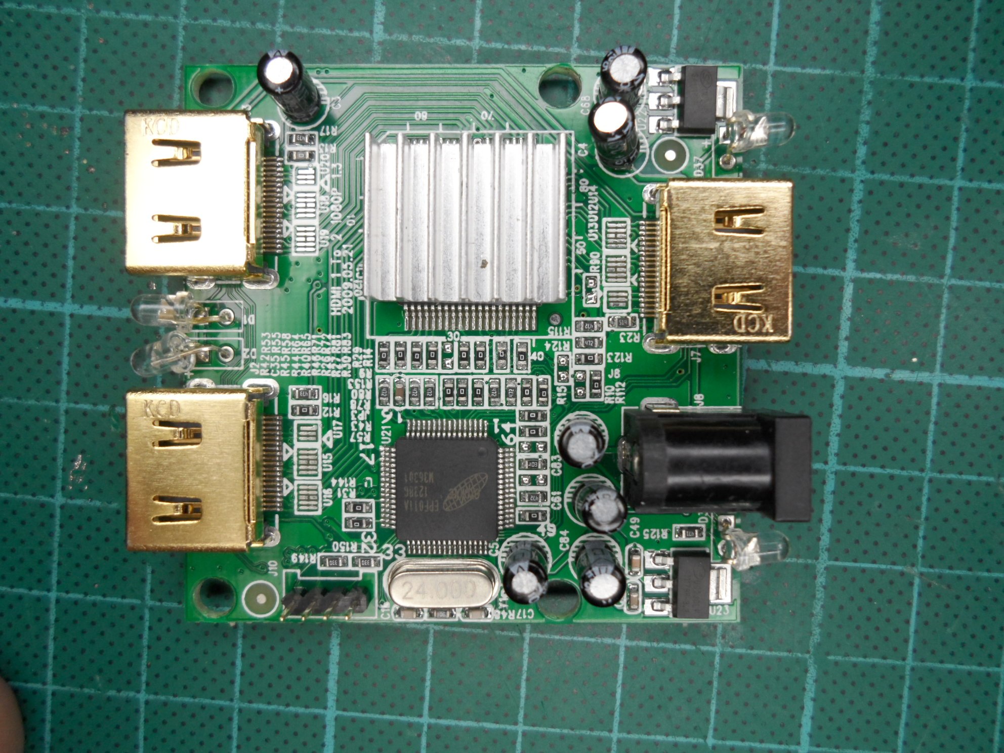
The datasheet for the EP9132 is fairly easy to find, and looking through it I could see that there really weren’t very many registers at all. Out of the few registers that there were, one immediately jumped out as interesting, bit 0 of register 0x0F (TX_ENC_ON), 1 = enable transmitter encryption, 0 = disable transmitter encryption.
As this was using an I2C bus where the data line defaults high, and the master and slaves communicate by pulling the data line low for a zero and leaving it to float high for a one, I thought I should be able to override any attempt by the microcontroller to set this bit to one by forcing the data line low at the right time. Then the microcontroller would think it had enabled encryption and carry on doing everything else it was supposed to be doing.
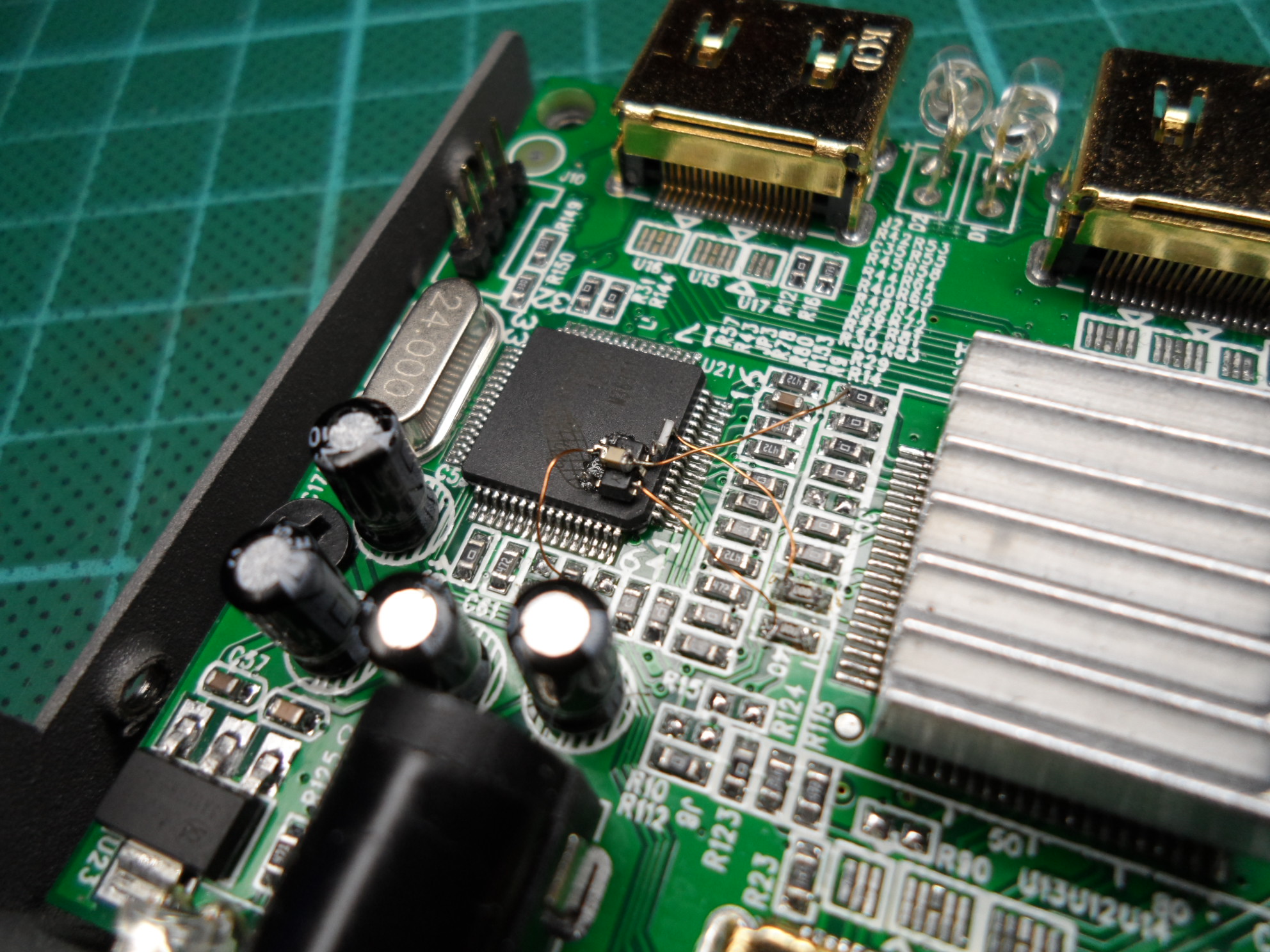
To do this I decided to use an Atmel ATTINY9 microcontroller, which is a tiny SOT23 package device with 6 pins, an internal 8MHz clock, 1KB of program space and 32 bytes of RAM. I connected the ATTINY to the splitter’s I2C bus and wrote some code to look for writes to register 0x0F, and force the data line low for bit 0 whenever it saw one.
Unfortunately this didn’t quite work. The ATTINY did successfully find the writes to the register, and it did succeed in forcing bit 0 low, but straight afterwards the microcontroller in the splitter would issue an I2C STOP where it never did before.
It turns out that the splitter’s microcontroller was doing exactly what the I2C specification says it should. Whenever it wanted the data line to be high it left it floating and watched for anything else pulling it low, when it saw me pulling the line low it detected a collision and aborted the transaction.
I2C Override, Take 2
Successfully Overriding The I2C Bus
One option would be to split the bus and have my microcontroller bridge between the two, that way the splitter’s microcontroller would be allowed to write a one to the bus on its side, but I’d write a zero to the bus on the other side.
The trouble with this approach is that it would be a lot more awkward to implement, rather than just soldering two wires to the splitter’s PCB I’d have to cut the traces, solder four wires and add another pair of pull-up resistors, so I wanted to try and find another way.
The next possibility that came to mind was overriding the I2C slave (the main splitter chip) instead of the I2C master (the microcontroller), would the slave detect a collision? Was there actually anything useful to override?
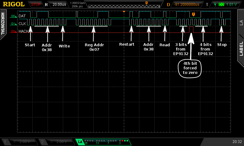
Going back to the datasheet, I found another interesting looking register, bit 4 of register 0x07 (RX_ENC_ON), 1 = receiver is decrypting, 0 = receiver is not decrypting. Sniffing the I2C bus with my oscilloscope showed that the microcontroller was constantly reading this register, so probably it would enable encryption on the outputs whenever it saw that the receiver was decrypting.
I updated the code in the ATTINY to target this new register, and… success! I got unencrypted output.
The image above shows this hack in action, the red trace is a debug signal from my microcontroller that is high while it is forcing the I2C data line low.
Hang On, It was Working A Minute Ago
Good Override
Late Override
Randomly Late
Now that I’d found a working hack, I moved away from the ATTINY on the breadboard that I’d been using to experiment and programmed another one which I soldered into the splitter, dead-bug style. I then took the splitter downstairs to my main TV to try it out, but it didn’t work. After a bit of fiddling about I discovered that it only worked on the first output, the second output was still encrypted.
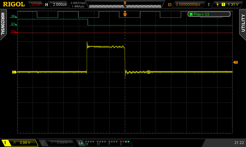
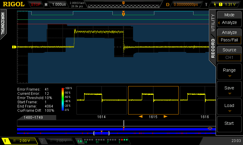
This shouldn’t have been possible, I was overriding all attempts to enable encryption regardless of the output port. Back up on the workbench I was eventually able to capture the problem on the oscilloscope. Occasionally, the override of the I2C data line was late.
The images above show this. In these images the top trace is the I2C clock, the one below is the I2C data line and the yellow trace is the debug signal that goes high while the override is in effect.
The left image shows a successfull override, the override begins in the middle of the low clock period and stays low until part way through the following clock low.
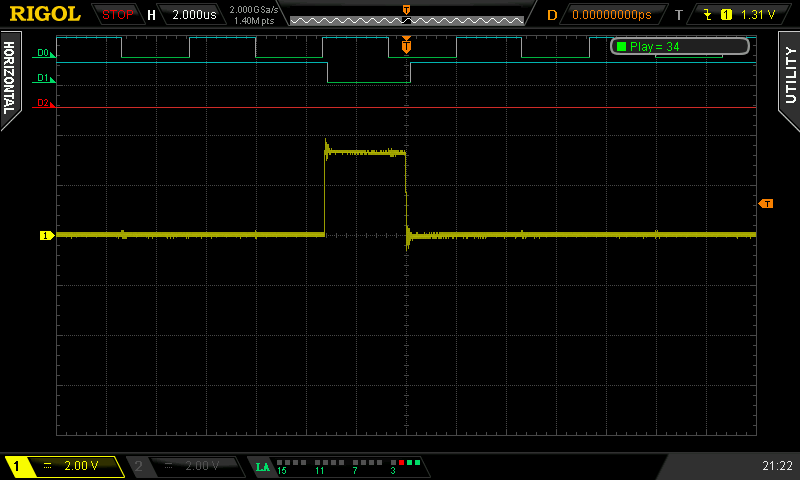
The middle image shows a late override. Here the override doesn’t start until after the clock has already gone high, which means that if the splitter’s microcontroller is reading the value of the bit right after the clock transition then it will see a one and not the zero I want it to see. Not only is it allowing the one bit through for part of the clock cycle, but having the data transition from low to high during the time when the clock is high is also an I2C START signal.
The right image shows how often the override was late. Out of 4096 overrides, 41 were late, and their distribution (which can be seen by the red parts of the blue bars at the bottom of the image) appeared random.
Decoupling & Series Resistor
I tried adding a decoupling cap across the microcontroller’s power supply, and I added a series resistor between the microcontroller and the I2C clock. This seemed to fix the one on the breadboard, but the one soldered into the splitter still had a problem.
Eventually I worked out what the real problem was… my microcontroller was a bit too slow. It turns out that with an 8 MHz clock the ATTINY doesn’t have very many clock ticks, and therefore instructions, for each clock on the I2C bus. In my code I had the following loop:
// wait for clk low
prevPins = pins;
while((pins = PINB) & PIN_CLK)
{
    // if data changes while clock is high then bail out
    // as it's a stop or a start
    if((pins & PIN_DAT) != (prevPins & PIN_DAT))
        return 0;
    prevPins = pins;
}
When the ATTINY was successfully overriding the bit, the clock was already low when the loop condition was first checked, and therefore the loop body was never executed. When the override was late, the clock wasn’t yet low and the loop body was executed once. With an 8 MHz clock the timing is so tight that executing those couple of lines in the loop body accounts for the observed delay.
The fix was simply to remove the body of the loop:
// wait for clk low
prevPins = pins;
while((pins = PINB) & PIN_CLK)
    ;
While this isn’t quite as correct as the original version as it won’t detect a START or STOP condition in the middle of the byte, that’s incredibly unlikely to happen, especially as this bit of code only runs during the transfer of the value of one specific register.
Fixing The Audio Return Channel (ARC)
Audio Return Channel Fix
Now I had both outputs reliably unencrypted and the majority of the niceties of HDMI were working. The TV was no longer switching to HDMI-1 when playing a Bluray, the TV remote could control the AV Receivers volume, the AV Receiver would switch to the TV input when running the iPlayer app on the TV… but I still wasn’t getting audio going back from the TV to the AV Receiver.
So, next I took a look through the HDMI specification (which is annoyingly hard to find a copy of) to see how the Audio Return Channel is supposed to work. From there I found that there were at least two things necessary for it to work:
- The TV and AV Receiver had to discover that they were both ARC capable via the CEC (Consumer Electronics Control) bus. This is the same bus used for all the on/off, input switching, volume control, etc. so that part should be working.
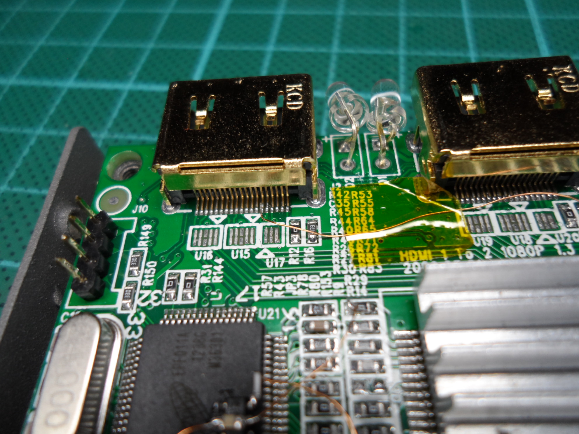
- The actual audio could either be transferred via a single ended signal using the Utility pin (pin 6), or it could be transferred via a differential signal using both the Utility pin and the Hotplug pin. Looking at the splitter PCB, I could see that the Utility pin wasn’t connected to anything, which certainly helped explain why ARC wasn’t working.
If the TV was using differential signalling then there wasn’t much I could do, the Hotplug pin is already in use in the splitter for it’s primary function, which is to indicate that a cable is plugged in and that there is something on the end of it, by being pulled up to 5V. Even if I properly understood how to mix half of the differential audio signal onto a line pulled up to 5V (which I don’t), I’m sure the necessary modifications to the splitter would be quite extensive.
However, if the TV was using single ended signalling then I should be able to simply connect the Utility pin on the input of the splitter to the Utility pin on output 1. After using a bit of enamelled wire as shown in the image above, I got lucky and it works!
Still No 3D

Dynamode Junk
Unfortunately, from what I could tell from the specs, this should just be a case of the TV declaring itself capable via EDID, and if that wasn’t getting through then the splitter most likely didn’t understand that part of the EDID data and wasn’t passing it through.
So the lack of 3D wasn’t actually anything to do with the hack, the splitter just wasn’t 3D capable. Which only left one option… try again with another splitter…
I did a search on Amazon for a HDMI-1.4 and 3D compliant splitter and bought a Dynamode 2 port splitter. Initial testing without the hack looked good, 3D and everything else (with the exception of ARC, but I knew how to fix that) was working. Inside there was an EP9132, excellent! But… just after I installed the hack MCU… one of the HDMI connectors broke! One of the contacts had de-laminated.
As I couldn’t really send back a unit I’d already taken a soldering iron to, I bought another one… only to have the connector contacts de-laminate after a single insertion! Don’t buy Dynamode splitters, they’re cheap and nasty junk!
So… this time it was off to Ebay, where I found an unbranded splitter that was apparently 3D capable and fully HDMI-1.4 compliant. Without the hack this one was doing 3D fine, but no ARC, and no CEC either. Looking inside I could see that both CEC and ARC pins weren’t connected, but both could easily be fixed with a bit of enamelled wire. There was an Explore chip set too, but this time it was an EP9142 rather than EP9132.
Updating The Hack For The EP9142

EP9142 HDMI Splitter Hacked
I went looking for a copy of the datasheet for the EP9142, which proved a lot harder to find than the one for the EP9132. I’ve still not found a downloadable copy but the Chinese Baidu search engine has a cached copy that can be viewed in its online PDF viewer (maybe there’s a download button there somewhere? it’s all in Chinese so I can’t tell).
The EP9142 has a few more registers exposed, but none of them looked particularly interesting. Eventually though, aided by finding a copy of the source code for the reference implementation firmware, I worked out what was happening.
As well as watching the RX_ENC_ON flag to see when the splitter chip is receiving encrypted content, the microcontroller in the new splitter was watching the RX_M0_RDY flag in bit 0 of register 0x40. This flag signals the end of HDCP negotiation between the receiver in the splitter chip and the video source. When the microcontroller sees this flag set it blanks the video output of the transmitters by setting TX_MUTE flag in register 0x08, and then begins an HDCP handshake with the devices connected to the transmitters. It only re-enables the video output by resetting the TX_MUTE flag once it successfully completes a HDCP handshake.
This explains why the TV was still getting a picture. It’s HDCP capable, so it completed the handshake and the output was un-muted. My HDMI Light on the other hand is not HDCP capable and would not have responded to the handshake, leading to the output remaining muted and the LED on the splitter flashing.
After updating the hack code to also override the RX_M0_RDY flag I was able to get unencrypted video output to any device.
Finally, Everything Works!
With that last change I now finally have a fully functional HDMI splitter that always outputs decrypted video. It has working CEC so on/off control, automatic input switching and AV Reciever volume control from the TV remote all work. The Audio Return Channel is working so the TV can send audio back to the AV Receiver, and 3D is working too.
The Files
The code for the ATTINY microcontroller can be found in my github repository here:
https://github.com/esar/hdmi-splitter-hack
Applying the hack should be as simple as programming an ATTINY9, connecting VCC and GND to a 3.3V supply within the splitter, connecting pin 1 to the I2C clock signal and connecting pin 3 to the I2C data signal.
The Splitters
In case it helps anyone find a suitable splitter here are the splitters that I’ve been using:
Neet 2 Way HDMI Smart Splitter
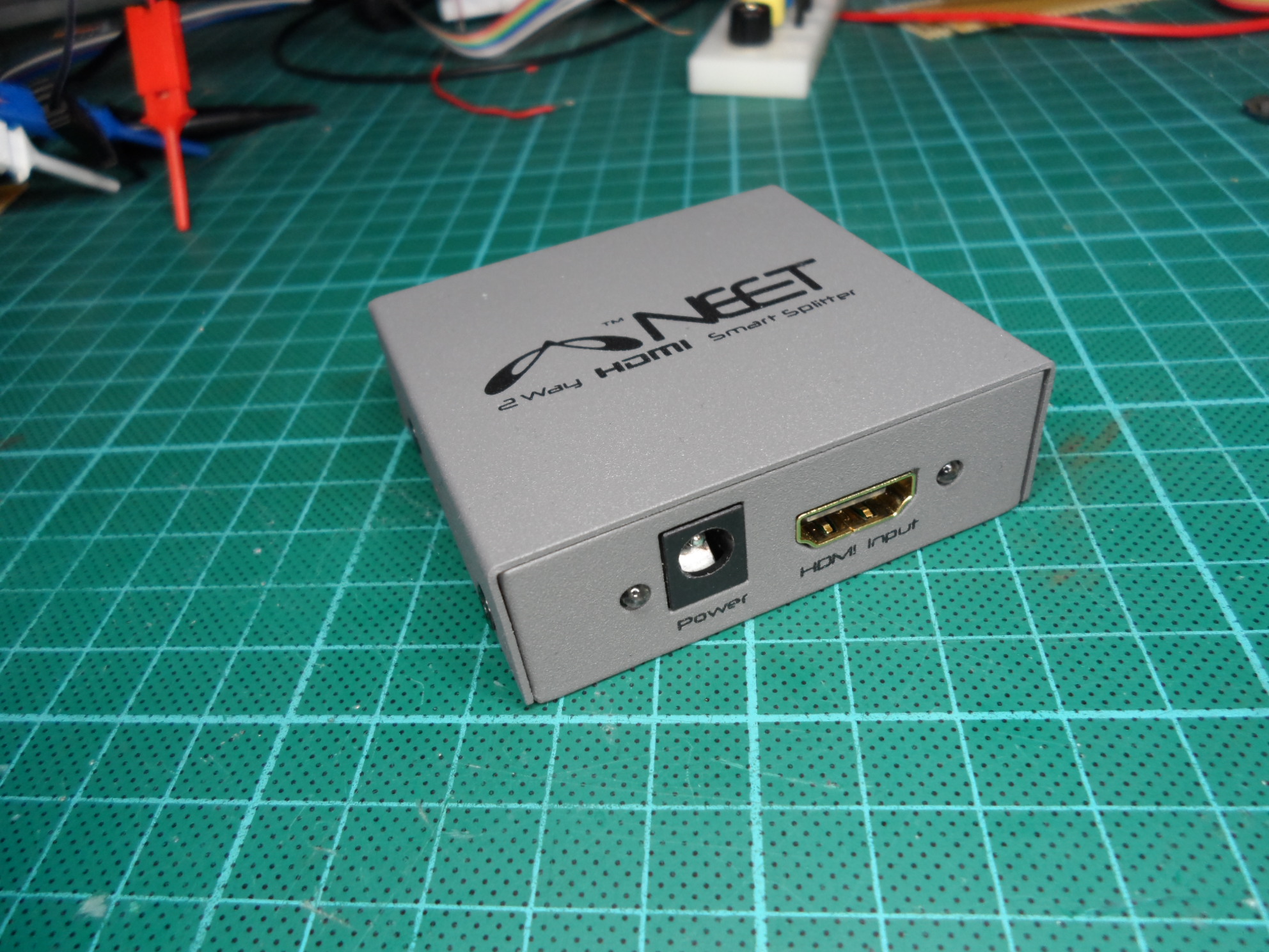
Neet Splitter
Neet Splitter Board
Dynamode 2 Port HDMI Splitter
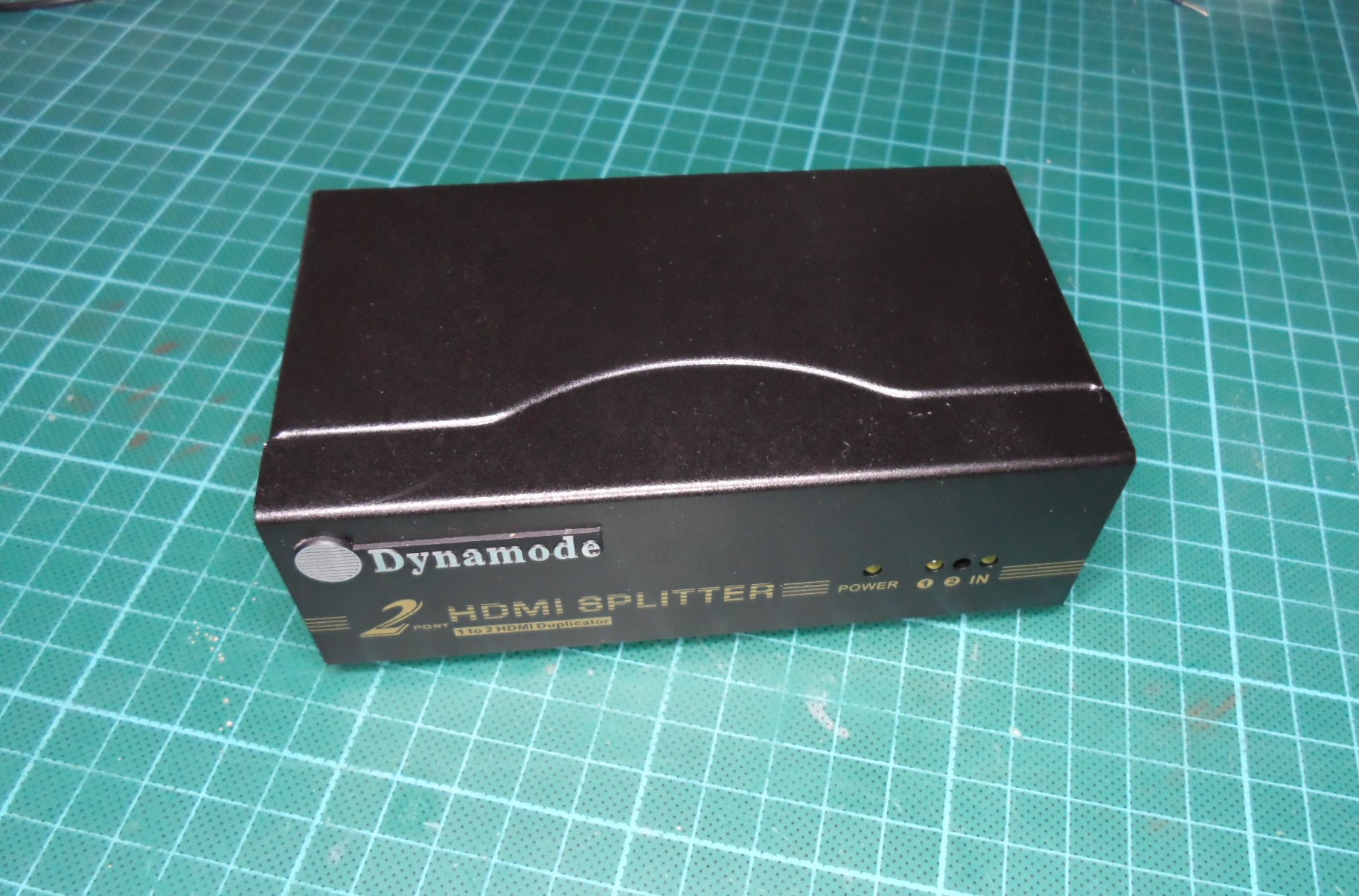
Dynamode Splitter

Dynamode Splitter Board
Unbranded Ebay Special
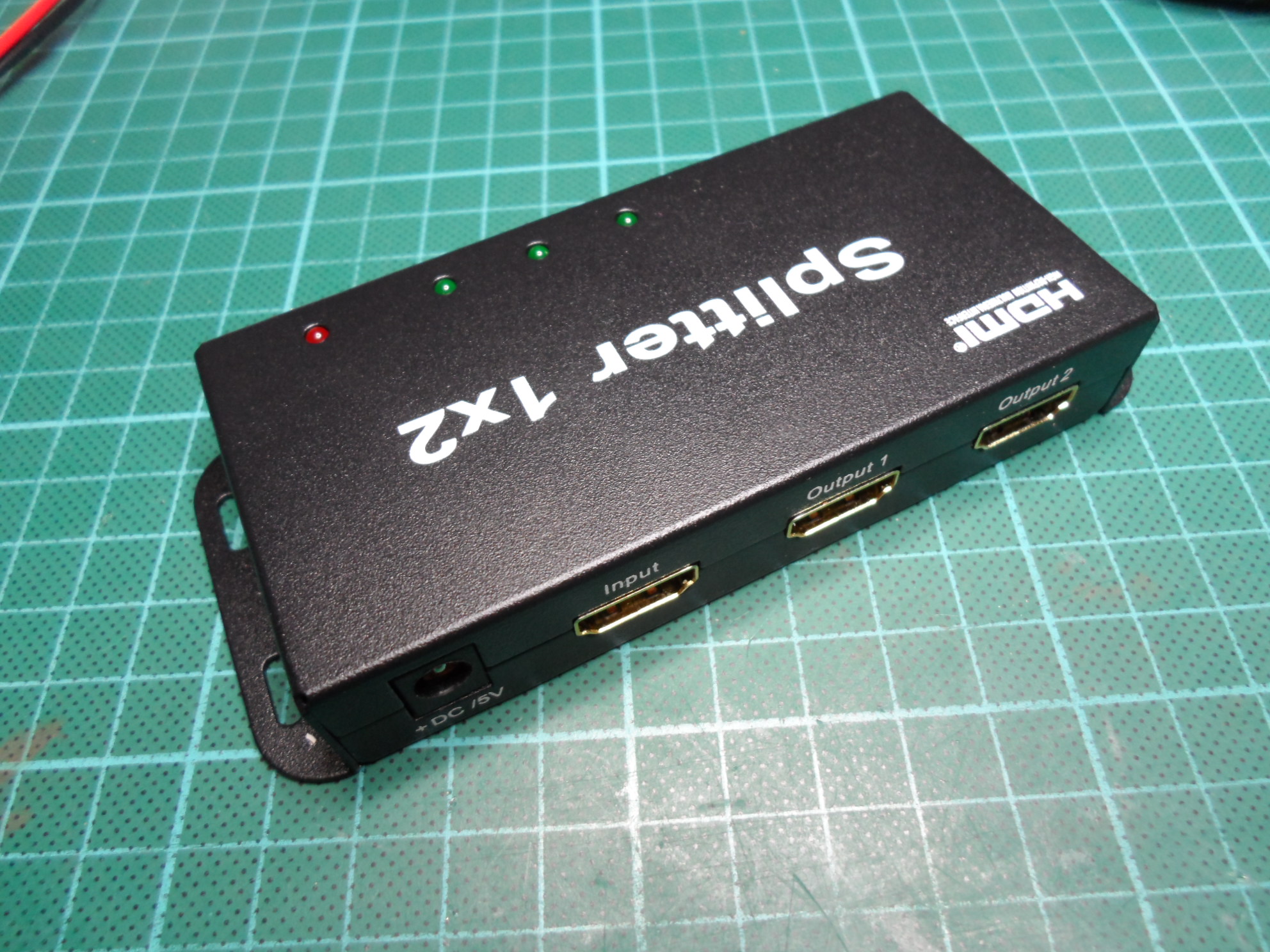
Unbranded Splitter
Unbranded Splitter Board
Pingback: HDMI Splitter is also a Decrypter | Hackaday
Pingback: HDMI Splitter Hack | | Heron | Scoop.it
(1) What do you think about the possibility of hacking the controller firmware instead? Since reference firmware is available, that should really help.
(2) What scope is that? The screenshots look nice.
I did briefly look into modifying the firmware but ran into two issues:
1) It’s setup to be built by a commercial tool chain, I spent an hour or two attempting a port to an open source compiler but got bored.
2) I’ve only found tools that can upload new firmware, none that can download the existing firmware. I’d really be happier if I could make a backup of the existing firmware before attempting to replace it.
The scope is a Rigol MSO2072A, hacked to enable 300MHz and all the options.
Pingback: HDMI Splitter is also a Decrypter | Hack The Planet
can you suggest an ebay seller for the unbranded one ?
The seller I bought it from was hdmultiroom.
If this link works, this looks like the same item from the same seller:
http://www.ebay.co.uk/itm/1×2-v1-4-HDMI-AV-Splitter-1-Input-x-2-Outputs-4K-Ultra-HD-PS4-XBOX-One-/161615243508?pt=LH_DefaultDomain_3&hash=item25a104e8f4
Pingback: HDMI Splitter Hack | | Digital Electronics &...
What about the Watermarking inside ? XD
Watermarking?
Hi, you may find the datasheet for EP9142 here http://www.datasheet4u.com/datasheet-pdf/YiShunElectronics/EP9142/pdf.php?id=906940
kavee
This is probably the same hardware as the one from ebay.co.uk mentioned above.
http://www.aliexpress.com/item/Powered-Splitter-Support-Ultra-HD-4K-3840-A-2160-Resolution-and-3D-Mini-HDMI-Splitter-V1/1963548101.html
I received the unit today. The Aliexpress was NOT the same internal hardware as the ebay.co.uk. NOT EP9142 in it.
Thanks for the update.
Anyone tried these tricks on the new Neet?
http://www.amazon.co.uk/gp/product/B001D9P1OW?psc=1&redirect=true&ref_=oh_aui_detailpage_o00_s00
Just ordered one, hoping for ARC being fixable like shown above.
Hi esar,
would you please give me a hint where to look for the source code you found?
I’ve got a device based on EP92A3E with integrated mcu (and another with EP91A1K and separate mcu).
The integrated chipset also has this wierd semicolon bootloader mode.. I’d really like to explore this one and any info on the reference firmware would really help – i’d at least expect broad similarities.
TIA!
It looks like they may have taken the site down, after a quick look on google I can’t find it.
I can’t remember exactly what I searched for in the past but it used to appear on google as a site with only an IP address and no domain name.
Send me an email (change the first dot in this site’s domain name to an at, so you get hacks at esar) and I’ll attach what I’ve got to a reply.
You may be interested in the firmware upgrade software at http://ap.koryo.com.tw/ . EPConsole is shown in the SIIG 1×2 HDMI Distribution Amplifier’s manual for upgrading the EP9142’s firmware. http://www.siig.com/download/search/?keyword=CE-H21A11-S1
This is really cool!
I am looking at achieving something simular with an hdmi switch in order to output the audio to my dac.
Perhaps i could pick your brain?
Kind regards
HDMI to VGA+TOSLINK+MiniTRS converters are around $15 for up to 1080p60: http://www.aliexpress.com/item//32247956757.html
If those are HDCP compliant, there’s at least two out-of-the-box non-compliant HDMI splitters starting at $7: http://goughlui.com/2015/05/05/teardown-analysis-unbranded-plastic-case-hdmi-2-port-splitter http://goughlui.com/2015/04/27/teardown-analysis-unbranded-metal-case-hdmi-2-port-splitter
The main audio signal isn’t easily available in the splitters, it’s mixed in with the video signal and spread across 4 very high speed serial links. You would need an HDMI receiver IC to decode and extract the audio.
Mahadri’s suggestion of combining an existing HDMI to VGA converter with a splitter is probably the easiest way to get what you want.
Having said that, if you’ve got any questions, I’ll try to answer if I can.
Martin, if you make any headway, please let us know. I just ran into an inability of my streamer to limit output to Dolby Digital 5.1 over HDMI, so color me intrigued by your plan.
Hi,
is the HDCP version of any relevance with these splitters?
I have a 4k TV but I can’t really use it because the new fire tv 4k can only output 4k material when connected to a hdcp 2.2 capable hdmi port.
Could your solution help me out, too?
The splitters I’ve been working with won’t help you as they don’t support HDCP 2.2, so your Fire TV won’t output 4K to them.
However, if/when a new HDCP 2.2 compliant version of these splitters is released they could be used to solve your problem, as long as the hack still works with them. You’d then have the Fire TV encrypting to the splitter with HDCP 2.2 and then an unencrypted signal with no HDCP out to the TV.
I don’t have any 4K capable equipment so I’ve never looked into it.
Hey, thanks for your reply.
I’ve already bought a splitter that, supposedly, supports 4k and HDCP2.2.
However the solution in the device is basically an analog switching IC that is able to handle the high switching speeds of HDMI.
So I guess no encryption magic happening there.
Although I saw that pericom also seems to manufacture some sort of HDMI protocol switches and splitters. Maybe I just have to find a device that uses one of these and give it a shot.
They also require a micro with I2C to controll it, so I guess it’s at least worth a try. 🙂
Nice! Is there a way to achive this with a HDMI Switch?
I’ve never looked at any switches, but if I had to guess then I’d say no. There’s no reason a switch needs decode anything, it can just switch the signals at an analog level.
Ok thank you for the information.
Hi,
I guess it all kinda depends on what the chip manufacturer wants to achieve.
I had a browse in pericom products and I found that there are different solutions to every problem. You can switch HDMI on a protocol level, then you need to decode and encode hdcp again, but you can also switch it on the analog level, which is what my switch seems to do.
Last solution is also a lot cheaper, so I guess most switches won’t be suited for what we are trying to achieve here.
Can anyone link to a good choice of EP9142 splitter now that’s it’s 2016? Cheers
hi esar i have souch project how to conact you i can pay u for that
Sorry, I have no spare time right now, paid or otherwise
Hi, esar! thanks for sharing your projects. I have a little question about ep9132/42. As I can see in datasheet there is no internal edid eeprom and no pins for external edid eeprom. As I can see ddc bus of hdmi source connected only to hdcp engine. Can you take a look on one of your splitters and say how they handle edid? Does external edid connected to the same ddc pins as a ep9132/42 hdcp engine?
Aslo there is no ddc bus on output hdmi lines at all, so it not just passing or copy one of sinks edid.
Can someone post a brand/model that uses the EP9142 chip? I mean brand and model, not a link. All those links are just expired now and unfortunately no way to locate an unbranded thing on ebay, amazon or alike. They don’t post the chipset in the sales page. Thanks!
Could this method be a possible way to get an ARC-TV working with non-ARC HDMI receiver and still preserve CEC?
Just get this one https://www.amazon.com/ViewHD-Powered-Splitter-1080P-Model/dp/B004F9LVXC/ and you don’t need to modify anything, read reviews. They don’t declare it as stripper, but it’s a fact.
I was just looking at one of my splitters at home to see if I can also “filter” out the HDCP.
While looking at the PCB, I can see I have an EPF021A.
Do you know if they are much different from the EPF011A you have seen?
Is there any documentation about registers/programming of the EP92A2E around…?
Hey there,
great hacks!
I just found out, that I had this first 2×1 splitter with EPF011A. I wasn’t sure which resistor you proposed to remove and where this pin was, which I should link to 3.3, and also didn’t know where to find this 3.3V.
Thus, I just removed the whole chip (you proposed that as third option), but unfortunately I don’t get an unencrypted HDMI output… well, it was worth a try.
I will buy another one, at least try to, and would be happy, if you could point out in your documentation, where to find this 3,3V or the resistor which to remove.
cheers,
Sorry, I can’t remember off hand which pins have 3.3v. The best thing to do would be to probe around with a voltmeter.
If you look at the photo at the top of the page you’ll see that the little microcontroller has two wires going to resistors next to each other, and the other two wires from the centre pins go off in different directions. One of those centre pins is going to 3.3v and the other to ground.
Aloha from the future 🙂
In case anyone is still interested, I have been able to extract firmware from an EPF021A, and re-program it without bricking: https://github.com/phlash/EPFtools
This is in pursuit of re-working the logic in a cheapo HDMI switch based on an EP94A1K switcher and EPF021A controller. I would really appreciate any leads on the datasheet for the EP94A1K though – all I have so far is the archive of the manufacturers info page: https://web.archive.org/web/20200329133507/http://www.epmi.com.tw/sayapro03.php?id=50 which at least has diagrams 🙂
mailto:phil.hackaday@ashbysoft.com please!