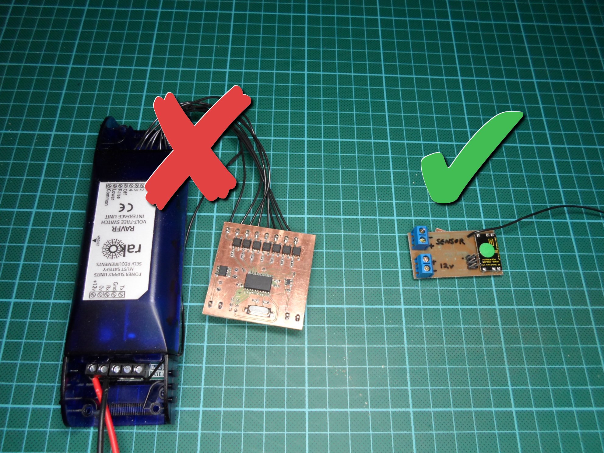
Now that I’ve reversed engineered the Rako protocol, I decided to redesign my touch switch controller so that it transmits Rako commands directly, rather than going via a bank of relays and an official Rako radio module. As the picture above shows, this results in a much smaller and simpler device, and also gives me a lot more flexibility in how the controller can interact with the lights.
Hardware Changes
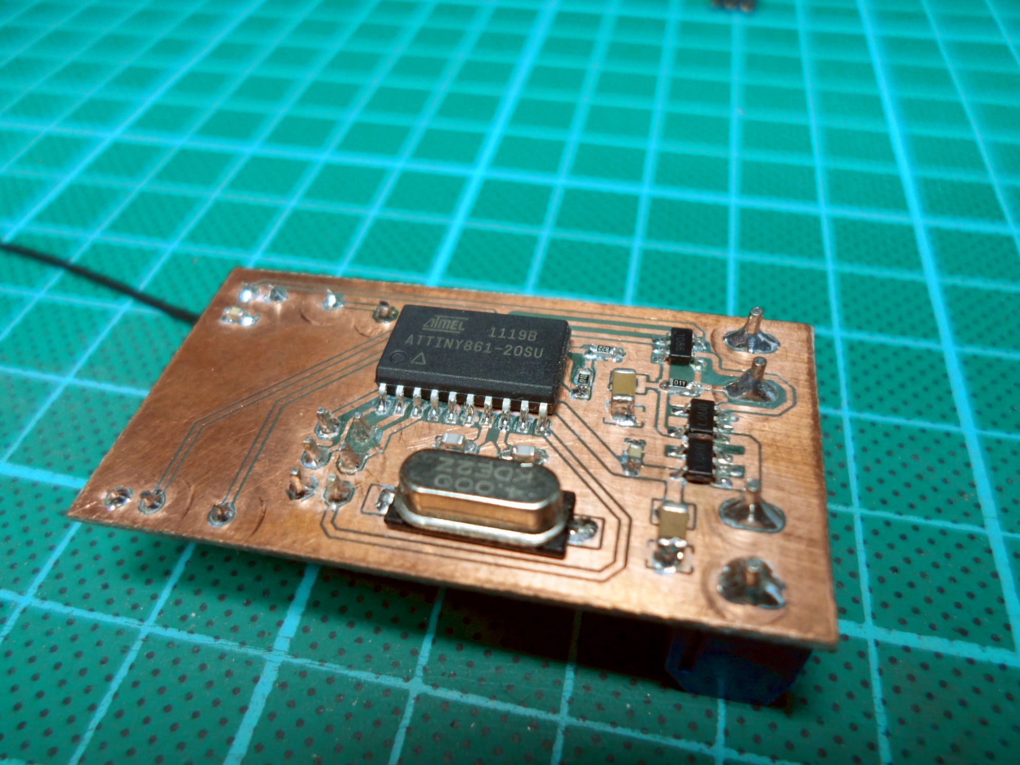
The most obvious change to the hardware is the elimination of the bank of seven solid state relays that previously took up nearly half of the board space. They’ve been replaced with a RTFQ1 433Mhz radio transmitter module, which connects to two of the microcontroller’s pins, one for the radio module’s enable input and the other for its data input.
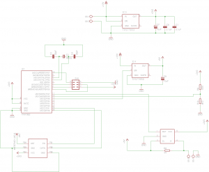
The radio module isn’t 5 volt tolerant so it has required the addition of a second voltage regulator, now both the radio module and the microcontroller are running on 3.3 volts. The 5 volt regulator has had to stay as the touch sensor still needs a 5 volt supply, it has however been changed to a smaller device, and where the sensor was previously powered from one of the microcontroller’s pins, it is now powered directly from the 5 volt regulator and the microcontroller controls the regulators enable pin.
The change to a 3.3 volt supply has also dictated a change in resistor values for the voltage divider that provides the reference voltage that the output of the current monitor is compared against. The resistors are now 100K and 8.2K to give a reference voltage of 250mV, which is half way to the expected 500mV that the current monitor should output when the sensor is activated.
Firmware
The main loop in the firmware is essentially unchanged from the previous version and is hopefully fairly self explanatory. It spins waiting for the state of the sensor to change and depending on the timing of the activation and deactivation of the sensor, it sends one of the five commands: scene1 (on), off, raise, lower, and stop.
Where it differs is in how the command is issued. In the previous version it simply pulsed one of the seven outputs to send the associated command, in this new version it has to send the Rako command itself.
To do this it uses the RakoMsg structure that was defined for the Rako protocol sniffer, setting the house, room and channel members to hard coded values and the command member to the appropriate command. It then calls the send() function to transmit the message.
The send() function is responsible for turning the message structure in to an array of bits that represent the level transitions that should be transmitted over the air. To this end, the first thing it does is append a preamble (101010) and start mark (11110) to the bit array. It then iterates through the 28 bits of the message appending the appropriate transitions for each bit, 10 for each zero bit and 110 for each 1 bit. After the message body it appends the check bit and end mark before finally calling sendTimerStart() to enable the radio module and start the send timer.
The send timer fires once every 544uS, every time it fires the radio data pin is set based on the value of the next bit in the array that the send() function created. Once the timer has fired for every bit in the array, the timer is stopped and the radio is disabled.
Files
Browse: repo
Recent Comments